|
Is currently awaiting the fitting of M030 suspension all round. The parts were sourced from Simon Butterworth at Porsch-apart. New bushes were ordered from Lancaster Porsche in Colchester. Fitting will be carried out with Peter Philips at Motorpreparation. When that's done, it's down to Northway Tyres in Colindale for a 4-wheel laser alignment. We'll probably change the brake fluid at the same time. I've just noticed a slight weeping from the flexible pipe attached to the clutch master cylinder. I'll order a replacement and we'll change it and bleed the clutch system the same time as the brakes.
My HKS CAMP data logger has now arrived, I'm assured, from Japan and should be fitted during the next couple of weeks, after which a lot of temporary wiring can be replaced and the interior steam cleaned and the leather Zymol'd.
The data logger on the SBC-Powermeter is recording very sub-5 second 0-50 MPH times with no real effort and without torturing the clutch. Hopefully a trip to Bruntingthorpe should allow updated timings and power measurements to be made after some remapping. The SBC-ID allows four boost strategies to be stored. I currently have two setup - the first peaking at 15PSI and the second with 10 PSI (lethargy mode !) that is OK for road (protect the license) use.
I am now getting a consistent 18 In Hg vacuum at idle, rising up to 22 In Hg on over-run with the new Purosil pipe-work in place. Fuel pressure is currently set to 31 PSI at 875 RPM idle, giving 1000 °F exhaust gas temperature. The Westach charge air temperature gauge has crossed needles to simultaneously indicate temperature in to and out of the Intercooler. Inlet temperature will very slowly rise to 70 °C after prolonged sitting in traffic, dropping to about 30 °C on light throttle. Intercooler outlet temperature is generally 20 °C lower under most conditions. Exhaust gas temperature hovers around 1,400 °C when cruising, rising up to 1,550 °C under boost conditions, at which point the charge air temperature can also rise over 100 °C.
The GPS calibrated speed readout shows the over optimistic nature of the standard speedometer. This is currently calibrated as it left the factory (180 MPH speedometer with Design 90 16" rims and Contisport 245/225 tyres fitted). I will create a proper table after Bruntingthorpe, but briefly a TRUE 70 MPH is indicated as 78 MPH on the speedometer (needle in the middle of the figure 8 in eighty), speeds above 20 MPH seem to read at least 5 MPH high.
I have been experimenting with an in-car APRS setup using a self contained GPS / NMEA unit feeding a Kenwood TH-D7G handheld with mag-mount whip antennae. I've also now got the Icom 706- IIG working on 2Meter and 70 cM bands with a glass mount antennae, and also have a very strong mag-mount that works really well with a Comet CA-UHV multi-band vertical for HF / 6M band.
I've started calibrating the HKS Camp data unit. The speed was set in KPH from the SBC Powermeter, itself calibrated against the GPS unit in the Alpine sat-nav. Both units agree with the GPS figure to within 1 KPH at 150 KPH, recorded in a straight line. The fuel / injector calibration will be calculated after a whole tank of petrol has been used, but again just about 1% accuracy should be easily attained. Unfortunately, changing the fuel pressure will require a repeat of the calibration procedure. I hope to fit the oil temperature sender over Easter on the ramp. The readings from the lambda sensor are very unstable so I think a replacement is in order - it is over 12 years old now and may be the cause of slight surging under high boost.
I've ordered a strut brace and gear quick shift for fitting over Easter with the M030 while the ramp is available. Should also change the weeping clutch pipe and change clutch / brake fluid at the same time. If time permits, I'll renovate the brake callipers at the same time as the suspension is off. I also ordered a new thermostat (lots of help from Lancaster at Colchester as always), but don't know if I'll have time to fit it at the same time.
Easter arrives and it's time to modify ! With the help of Peter Philips at Motorpreparation, the M030 suspension was fitted with new bushes as appropriate. Unfortunately I managed to damage the pipe between the O/S/F brake calliper and bracket on the strut when trying to remove a corroded clip, so Pete made up a new pipe on the spot. When all the suspension was replaced, we changed all the brake fluid and bled the entire system. The pedal now feels a bit more solid.
Good Friday's first job was to fit the gear change quick shift linkage that I didn't have time to do on the ramp. This is a replacement of the standard gear linkage on the top of the gearbox which reduces the throw of the gear lever by 30%. This is easy to fit from a ramp, but a real pain without ! I also changed the nylon bush that the ball at the bottom of the gear lever pivots in, as this had some wear. The end result of this is a much tighter, shorter and more precise shift, and the SBC power-meter is now viewable in 5th gear !
Next job was to take the wheels off and do a thorough steam clean of all four arches, front suspension including the trailing arms and power steering pump and sump. At the rear, the gearbox, diff and gearbox oil cooler were also steamed clean. The inside of the wheels were also done before the wheel studs were then lubricated and the wheels torqued back on. Finally a quick blow over the sides of the engine bay to clean up and brake fluid spill from the previous night's brake bleed session and power steering fluid from the reservoir expelled when the rack was moved manually when fitting the front suspension.
Saturday morning was the trip to Northway tyres in Colindale for a 4 wheel check and alignment. They have probably the best equipment available, the Hunter DSP400 alignment rig, if fact they've got two of them !
The car was driven on the ramp and the calibrated reflectors were mounted to all four wheels, then the car raised on the ramp. The Hunter fires infra-red light at the sensors, which is then picked up by 4 cameras on the top of the rig. The video from each camera has it's own DSP (digital signal processor) and from this, the computer gives real time readout of toe angle, camber, cross camber, caster, cross caster and thrust angle !
I had the settings reset to factory defaults, except front and rear camber, which were set to 1.5 negative at the front to match the rear. These are my initial settings to set up handling while the shock settings are tweaked.
The suspension is still settling slightly, but the whole car now feels much tighter, controllable and provides more feedback through the steering without being too harsh on motorway and white surface. It also seems less susceptible to tram-lining. The strut brace has probably helped here too, particularly through tight corners.
I finally replaced the clutch fluid flexible hose and fluid. It is possible to bleed the clutch without removing the starter motor, but it is much easier on the ramp. A 7mm spanner is needed for the slave cylinder bleed nipple.
Had a near disaster this morning (27/04/2003). Got 200 yards from home and the oil pressure light came on and the gauge plummeted to 0 ! I stopped and checked the dipstick - plenty of oil and none on the ground, wires on the oil pressure sender unit. Started up again and the light stayed on. Drove back home 200 yards and could just see a pulley at an angle by peering beneath the air filter. I had to leave the car for the day as I was booked on the annual JEC London-Brighton run in the Daimler. When I got back, I took the air filter off and found the power steering pulley rolling about in the under tray ! The crank pulley bolt was completely missing. Disaster - had it sheared off, meaning a complete engine out and possible new crank ?
I managed to 'borrow' a crank bolt and washer from another 944 owner who had an engine in bits, hoping to see that the bolt would thread all the way in. When I opened the bonnet, I found my original crank bolt and washer at the end of the under tray, and in tact ! I refitted the power steering pulley and torqued the bolt down as much as possible from above, crossed my fingers and started the engine - I got immediate oil pressure and the tappets had pumped back up within about a minute !! A very lucky escape indeed. I got the car on to a ramp and dropped the under trays to get at the bolt from below with a 24" extension to tighten it back up and refitted the power steering belt. I'll certainly make sure I check this bolt on both 944's from now on when they're on the ramp.
I've now fitted Magnecor 7mm spark plug cables, and replaced the lambda sensor while on the 4 poster ramp. I also checked the tightness of the suspension mountings. The A/F ratio is still not stable so it's time to test the TPS, air and water sensors.
I replaced all the M6 nuts and captive nuts that secure the engine under-tray. I also loctited the allen screw that secured the quick shift linkage to the gear selector shaft in an effort to prevent it from coming undone. The oil was changed to Magnatec and the gearbox was drained and refilled with Swepco (courtesay of Bert at Berlyn Services).
I've now adjusted the mixture to 1.5% in the open loop state by adjusting the AFM with a revised fuel pressure. Closed loop state is still a solid 0.5%. I also re-oiled the K&N air filter cone after steam cleaning the engine bay after the oil change.
After a lot of enquiries, I cannot get any 18" rims to my liking to fit the Porsche PCD. Preferred were OZ magnesium or Dymag 5 spoke. As an alternative, I'm trying to get some 18" cup 1 wheels. My existing design 90's might get refurbished and go on to the 944 S. The big rims will pave the way for the next mods - big brakes, either big red's and 996 Turbo discs, or a complete AP setup with 6 pots.
Turbot has now joined toe 100,000 mile club ! I have looked further in to the wheel situation and decided to go for 20002 Carrera type 5 spoke 18" rims. more to follow on this ...
Update. The Carrera wheels and tyres are now fitted. No clearance problems. I've now got room to upgrade the brakes ... Game on ... now on order big reds (993TT) and c2 turbo 3.6 322mm drilled discs.
08 & 09 August - big works afoot, with the help and experience of Peter Philips at Motorpreparation. The rear discs were removed and the calipers were painted red. The front discs and calipers were also removed to make way for a big brake conversion. This consists of 322mm x-drilled discs from a c2 Turbo 3.6 and big red calipers from a 993 TT.
The calipers are a direct swap for the 928S4 calipers fitted to late spec 994 turbos. These also come as 'big blacks' as fitted to the 928 GTS. The difference is that the big reds are designed for leading mounting (ahead of the axle) 911 applications, while the big blacks are trailing mounting, as used on the 928 and 944. Although the big blacks are a direct fit on the 944, I chose the big reds and converted them to trailing mounting by swapping the bleed valves and crossover pipes, so that the bleed nipples remain at the top when the calipers are inverted for their new trailing position. No new solid pipes were needed between the back of the caliper and the strut.
The choice of discs is limited to 968GTS, 993TT or 911c2 3.6 turbo. The 928GTS discs are non x-drilled. The 993 TT discs need a 5mm 'hat' adaptor, but the c2 discs have the correct offset. I decided on the latter as a direct replacement, although they work out slightly heavier than the 993 TT discs / alloy spacer ring. I had to dispose of the rear stone shield for the discs, as the new ones are larger ! To do this, first the hub is removed, then the backing plate removed. This was then cut down with tin snips and replaced, continuing protection for the ABS sensors. The front hubs and bearings were then checked and re-greased. The new pads and sensors were then fitted. The rear discs were replaced with x-drilled items, pads and sensors fitted and the whole system thoroughly bled and tested for leaks.
I had already painted the hub parts of all discs with matt black high temperature paint to prevent the formation of rust and make the whole setup look cleaner.
The air-conditioning was the next to be attended to. A replacement compressor was recently bought from Porsche-apart. This was sent to Mirage Air for fully testing and servicing before fitting. Lancaster OPC provided a new receiver/dryer and new seals for the dryer and compressor. With all new parts fitted (the condenser and pipes were replaced last year, but the system not gassed or run), the car was taken to Alpinair in Stanmore for a completion of the conversion to R134a refridgerant.
The necessary valve converters were fitted and the system thoroughly vacuum tested for 30 minutes to make sure that there were absolutely no leaks anywhere in the system. The new R134a gas was then introduced and the system thoroughly tested. It now performs perfectly ! While the air conditioning compressor was removed and the power steering belt also out of the way, the front timing covers were removed to change the timing belts.
Although the cam belt was in good condition, if slightly slack, the balance shaft belt had broken !!! On examination, 3 teeth were missing one one side and the belt had given up !
After a huge sigh of relief that there had been no other damage done, the cam belt was also removed and all the rollers checked and found to be OK. The water pump was also checked for telltale signs of leakage, none were found and no water is being lost. The new belts were then fitted and tensioned.
The oil was drained and a modified sump plug with temperature sensor fitted. A new filter and Magnatec then completed the works.
While changing the front brakes, a camber bolt on the OSF strut was found to have loosened, allowing play and variable camber ! This was tightened up, but a visit to Northway Tyres the following morning saw a full geometry check. The only setting that had changed since the recent full alignment / adjust was that strut. The setting was adjusted and everything re-checked by Andy. The new Pirelli tyres should now be safe !
The car in now bedding in the brakes, This should be done in time for the Tuesday night Essex PCGB meet (12/09/03) and the London PCGB meet the following night !
Update. The brakes are now bedded in and performing as expected - much better retardation and less fade are immediately noticeable. The pedal now provides a lot more feedback. The car now has a much improved stance due to the new wheels & tyres. I haven't noticed a significant increase in tramlining, and black tarmac is not much louder than on the previous wheels & tyres. White tarmac is horrendous (although I've noticed the same in all my cars !) with very loud road noise.
18/08/03 The next stage of engine development is currently underway. Dave Lindsey (Lindsey Racing) has supplied a matched set of 55 lb/hr fuel injectors. These will be run with a fuel pressure increased to 3 bar, giving a lot more headroom as the injectors have been reaching saturation at peak power. A new induction and metering setup will shortly be fitted, along with a significantly better turbocharger than the standard KKK K26/8, and uprated Lindsey Racing intercooler. A completely revised engine map should see a significantly increased power capability.
22/08/03 A stage II intercooler has been ordered from Lindsey Racing, and am still waiting to finalise the turbo spec with Dave Lindsey.
A GURU racing MAP2 kit with hand held programmer, serial data-logger and Lambda-Link air fuel ratio gauge are now on order. The gauge will replace the K&N LED version mounted to the side of the centre console, and work in conjunction with the data-logged display on the HKS camp.
The GURU kit has a single 4" pipe & K&N filter relocated behind the N/S headlamp. This allows ditching the restrictive 'barn door' (standard 952) AFM and leaky J pipe. I have also got another badge panel now ready to cut cooling slots for the intercooler. I'm hoping to drop the charge air temperature right down and reduce a large amount of restriction all the way from atmosphere to the throttle body.
A 968CS adjustable rear spoiler has been located and is on the way and will be sprayed before fitting.
29/08/03 The Link Electronics illuminated air / fuel ratio gauge is now fitted.
I bought a LRC100 laser diffuser at Eynsham, so that will be fitted in the front air dam when the intercooler is changed and the modified badge panel fitted. I also bought a road pilot, but will probably share that between the 944S and the Daimler, leaving the Morpheous Geodsey in the Turbo.
The road pilot seems a permanent feature now ! It works really well.
I have fitted the Lindsey Racing supplied 55 lb/hr fuel injectors. A very easy installation that took about half an hour. What took longer was installing the GURU Racing chips, not because of fitting the chips but getting access to the DME/KLR through the additional wiring in the passenger footwell. I am still awaiting many things from Danno at Guru Racing, including the MAP2 kit and programmer, and info as to which strategies he has actually programmed in to my chipset for which I asked for both standard and #55 injectors and K26/8 and K27/8 turbo.
I have bought a wideband O2 kit from PLX Devices www.plxdevices.com . This has a wideband Bosche sensor, wiring loom and electronics module that provides outputs for both wideband and narrow band. This sensor is a direct replacement for the standard 944 Turbo sensor in the exhaust downpipe. The new loom will be fed through the bulkhead and the narrowband output used to feed the DME, HKS Camp data-logger and Guru MAP2 kit (when it arrives). The wideband output will feed the Link AFR gauge in wideband mode to allow much better resolution (+/- 0.1) resolution between 10:1 and 17:1, and allow much more accurate tuning with the link programmer when it arrives with the MAP2 kit.
The PLX M250 converter and wideband sensor is now fitted.
08/02/2004. I finally got around to installing the stage II Intercooler that I bought from Lindsey Racing last August ! Total time to install was about 2 hours as I carried out other works at the same time. No problems with the installation thanks to clear instructions on the LR website. A test drive (in highly dense air) indicated solid boost and a faster spool up time. Must have been helped by the weather because the car seemed to fly !!
Tried a bottle of Wyns Hydraulic Lifter Treatment. Seems to work well.
01/04/2004. The saga of the LambdaLink AFR gauge is now over. The gauge was sent back to Link in New Zealand to be reprogrammed. This was needed as the wideband calibration was inverse, 0-5v instead of 5-0v. This took a long time to resolve, but thanks to Walter at Link, all works properly now. I have also replaced the blue purosil hose in the booist control circuit with Aeroquip braided hoses. When using boost over about 15 PSI, the purosil seemed to be ballooning and allowing unstable boost control. The Aeroquip has now bought this under control.
29/04/2004. A spare cylinder head, inlet manifold and cam/tower have been sourced from Porsche-Apart. These are now at CTM heads in Ilford (who have done all my cylinder head work for the last 10 years). The head will be stripped and cleaned, crack tested etc. New valve guides will be fitted, along with bigger inlet valves. The inlet ports are being taken right out and polished. Five angle valve seats are being cut. The exhaust ports will remain pretty much standard (retaining the ceramic liner) with just minor smoothing and possibly replacing the sodium filled exhaust valves. The inlet manifold will be honed and blended before being port matched to the cylinder head. The throttle body will also be improved with radius and knife edgeing. It will also be modified around the throttle spring mechanism to allow the fitting of a T04E turbocharger underneath. A modified cam profile is under investigation at the moment as well. When completed, the inlet manifold and tower will be powder coated.
04/06/2004. Test fitting of a 944 2.7 inlet valve in to the turbo head is a success. This valve is 3mm bigger (48mm). This, in conjunction with the Lindsey Racing Titanium valve retainers should remove a considerable amount of weight from the valve gear, giving much greater air flow and allowing a higher rev limit. UPDATE: std valve+retainer = 132.65g, 48mm inlet valve +LR titanium retainer = 129.35g, a weight saving of 3.3g per inlet valve assembly.
The inlet valve seat inserts are being replaced with bigger versions to fit the enlarged valves. Initial enlargement of the inlet tract is completed. Final works will see enlargement and smoothing to inlet gasket size. The exhaust ports have the ceramic liners intact, and have has a good cleaning and tidying. The inlet manifold has had a lot of internal metal removed from the casting to get rid of rough edges and increase tract size. The inlet manifold is also being drilled and tapped to accept a Bosch air temperature sensor to experiment with the DME programming relating to charge air temperature.
Interestingly, a Lindsey Racing head with big valve conversion (stage III) flows 39% more air (252 vs 180 cfm) in the inlet, 190 cfm exhaust.
After a long phone call to Dave Lindsey, the turbo has been ordered. This will be a LR Super 75 Turbo, retaining water cooling and with a #8 hotside. This is a Garret T04E turbine with 67mm compressor and will flow 1,088 cfm (standard turbo/250 uses KKK K26/8 which flows about 367 cfm) at 1 bar boost.
I'm replacing my standard fuel injection rail (currently fitted with LR adjustable FPR and fuel pressure gauge) with the LR billet fuel rail. This runs much cooler and has better internal fuel flow and distribution to the individual injectors. It has the fuel damper mounted directly on the end, and the large capacity adjustable fuel pressure regulator is mounted remotely in the engine bay with integral fuel pressure gauge.
Because of the increased boost (and therefore crankcase pressure from blow-by), and because it's not very efficient to combustion to vent pressurised oil vapour directly back in to the inlet, I'm fitting an LR remote oil catch tank and vent system. This will also allow more of the 'knitting' under the inlet manifold to be removed.
07/06/2004. The Lindsey Racing delivery has arrived (4 days after ordering !!!).
I installed the 'Flamingeye' LED instrument cluster kit. This uses LEDs to illuminate replacement lenses at the edge of the instrument cluster. This is an easy kit to install and replaced the factory bulb and silver-coated plastic lenses that crack and break down over time leading to the familiar dim illumination on 944's. The LEDs are available in a number of colours. Mine are high UV content blue.
14/08/04. The Lindsey Racing billet fuel rail is now fitted. The old fuel rail came off complete. The new rail went on with the #55 injectors. Because the LR kit is designed for LHD cars, the remote fuel pressure regulator and pressure gauge mounting have been changed to fit my RHD car. The pressure regulator is mounted directly to the inner wing, just behind the clutch reservoir which remains in it's original position. There's not, however, space to mount the fuel pressure gauge (removed from the front end of the original fuel rail) directly on the pressure regulator. It has been mounted directly in to the fuel damper instead, replacing the Schrader valve. On USA cars (and also on UK 1998 turbo's such as John Sims) the flexible fuel pipe between the existing fuel rail and the hard lines from the rear of the car are crimped just inside the engine bay. This would have required removal of the O/S inner arch liner and cutting the existing 6 & 8mm steel hard lines and using the (LR supplied) compression fittings to make the now flexible pipe ends. On my 1990 turbo, the hard lined terminate on the engine side of the inner wheel arch with male -6 & -8 couplings. I therefore didn't have to cut my lines and use compression fittings, but just used -6 Aeroquip fittings and steel braided piping. I also replaced the existing -6 Aeroquip for the boost control with smaller -4 and changed the pipe-work routing from the boost pipe.
12/09/04. Lindsey vented headlamp cover is now fitted.
14/09/04. More goodies arrive from Lindsey Racing. Vernier adjustable cam gear allowing 4 deg retard - 6 deg advance adjustment of cam timing. KISS oil cooler kit with 11 row remote radiator to keep oil temperatures down (up to 55deg reduction). CM billet oil filter with replaceable 8 micron filter. Siemens powerpack matched #72 injectors (#55 currently fitted, standard are #34.5). New coolant header tank. Raceware head stud kit and Widefire head gasket. Bosch high volume fuel pump. I have now also sourced a 924 Turbo (931) bonnet, complete with NACA cooling duct. A 931 complete badge panel and vents. Also a spare N/S metal headlamp cover to modify with NACA ducts to replace the Lindsey Racing one.
18/11/04. After having a boost pipe blow off, I decided to carry out a full check of the clamps and general air-tightness, including all the vacuum lines. I have been getting sporadic over-boost for some time and wanted to get to the bottom of it. Using a combination of a footpump with pressure gauge and several types of purosil hose, a vacuum pump and some smoke matches I found a number of small leaks.
Firstly I had been getting a hiss during boost from behind the instruments where I have a number of sensors for the SBC-iD boost controller, HKS camp and feed to the A pillar mounted boost gauge. These are all fed by a single purosil feed through the bulkhead. I had used a number of adaptors to link all the necessary pipes, but these were now worked loose and starting to leak. A change to the plumbing means that this segment now holds 20 PSI indefinitely.
I then checked all the heater control and vacuum reservoir segment, which had no leaks. Likewise the non-return valve (blue/black plastic) was fully functional.
Next up, the vapour purge / dump valve. This was leaking quite badly from the dump valve when over 10PSI was applied. This is a Bailey DV vent to atmosphere piston type valve. I stripped it down and cleaned the piston sealing ring and the rest of the internals. This is now performing as it should. The next leak was from the metal fuel purge valve where the purosil joined the nipple. Not wanting to use cable ties to secure the purosil, I looked for an alternative.
A phone call to John Sims about the number of small leaks found us discussing a better way of sealing the purosil. John came up with the excellent idea of tight rubber O rings rolled over the joint. A quick rummage in the spares rack found a whole load of suitable rubber rings. I have fitted 2 to a number of places where the purosil vacuum hoses fit over connection nipples, such as both vapour valves, dump valve, fuel pressure regulator etc.
This has bought about a remarkable improvement as all the small individual leaks add up to quite a loss ! I now have 20 hg of vacuum at idle again.
Next up, I thought I'd pressure test the boost control circuit. I have an EBC fitted and this is still fed from the banjo on the boost pipe, via small bore Aeroquip hose to the boost controller and finally to the Lindsey dual port wastegate.
There was a considerable leak coming from under the car in the wastegate area. Putting the car up on the ramp and dropping the undertray revealed that the nipple on the top of the wastegate had worked loose. I disconnected the Aeroquip pipe and tightened the brass elbow adaptor further in to the wastegate then reconnected the pipe. A new pressure test from above revealed there was still a significant leak. Moving the Aeroquip pipe around revealed the reason
The Aeroquip had moved around and got too close to the the exhaust flange at some point and melted some of it's internals. In one position the pipe was leaking badly, in another position (small change) the seal was good. At last a reason for the intermittent boost control ! I replaced the section of Aeroquip between the boost controller and wastegate, and rerouted it further away from the hot areas, cable tying it in place. The final pressure test shows slight leakage from the wastegate itself. A discussion with John Sims again confirmed that his Tial wastegate also leaks copious amounts of air from the control lines!
A final road test shows that vacuum is now much better, maxing at 22 Hg on the overrun and 18-20 Hg at (hot) idle. The boost controller is now able to to control down to a rock solid 7.2 PSI. I haven't tested the upper limits yet because it was absoloutely pouring with rain and I was on the North Circular Road in quite heavy traffic.
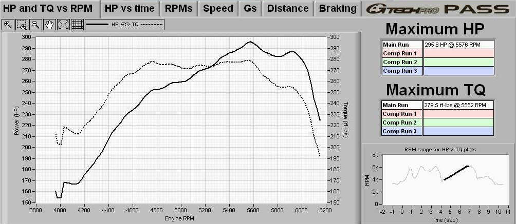
I have now fitted a G-Force RR performance analyser http://www.gtechpro.com/. In pouring rain, with 7.2 PSI boost I managed 0-60 8.28 sec, 157.8 BHP @ 4869RPM, 179.6 ft-lbs @ 4477RPM. This is RWHP. I'll be able to put some proper figures out when I've weighed the car accurately and got some decent dry flat road !
A more recent snap-shot graph taken without and special preparation. This is from G-tech RR and represents RWHP. More fine tuning has taken place since to adjust fuelling around 4000 & 5000 rpm to fill the curve out more.

I've sourced a separate vacuum manifold to tidy up the control signal routing in the engine bay. It six ports, all fed from a single banjo bolt on the inlet manifold.
04/04/05 The throttle body is now finished. The (3) fibre seals on the throttle body were decomposing, allowing an air leak past the throttle spindle bearings. These fibre seals were removed and replaced with rubber o rings. The throttle plate screws were also shortened to be flush with the spindle, further increasing airflow.
06/04/05 A new order has arrived from Lindsey Racing. Order placed at 22:15 on 04/04/05, arrived at 09:00 06/04/05 - unbeatable service all round. The order consists of the in-line turbo oil filter kit, a pair of Supermount engine mounts and a pair of adjustable camber plated with spherical mounts.
08/04/05 Work has finally begun on the big conversion ! Works are being carried out at Motorpreparation by myself, Pete Philips and (occasionally) John Sims. Custom wood chocks have been built to protect the underside of the Porsche on the two poster ramp. Wooden ramps have also been made to drive the car on to while positioning the ramp arms in order to properly clear the body rubber side skirts. The bonnet and under trays were removed. The battery disconnected. The engine set to TDC. During the rest of the day, the engine bay was stripped of air intake, hard pipes, injection system & boost control, inlet manifold, water pump, timing belts, rollers and tensioner, cam tower, expansion tank, alternator.
The head was removed complete with the exhaust manifold. The front wheels were removed, as was the N/S inner wheel arch liner.
The condition of the head was excellent. Looking in the inlet ports shows clean ports and valves. The inlet tract was a light brown varnish colour. The exhaust ports and valves also look in good shape. The top surfaces of the block also showed no signs of problems or leaking head gasket (the car looses NO water and minimal oil, except through a leak that was revealed when the under tray was removed and found to be the sump drain plug weeping). The turbo charger is also in remarkably good condition with virtually no play in the shaft bearings. As for the bores, they are all clean with no scoring at all. No problems with wear ridges either. Just a good carbon seal around the top rings. The piston tops also look in very good condition.
Problem No.1 was found when we tried to remove the head studs to replace them with Raceware items. We could not shift the first stud we tried - No.1 cylinder. Despite me using two locking nuts with a second spanner extending the first for more leverage, and Pete using a pair of mole grips at the bottom of the stud at the same time, the stud just would not shift. A quick call to Jon Mitchell saw us heating the stud and block to try to break the seal. All we succeeded in doing was to bend the stud. Time for a rethink. If we sheared any of the studs, the block would probably be scrap. A call to Lancaster OPC at Colchester found that they had one head stud in stock. This was ordered , along with some other nuts, bolts and studs for the exhaust system among other parts and was to be ready for collection on the following (Saturday) morning.
The revised plan now was to somehow get the damaged stud out. This we managed to do after a lot of heating the block around the bottom of the stud with a blow torch. It still took two of us to get the stud out. The 944 has very long studs for the head and the bottom thread of these are sunk deep down in to the block. With the engine in the car, there is no easy way to get enough heat in to that direct area of the block, particularly as there is not enough clearance in the engine bay to get at the rear of the block without melting something. Jon Mitchell had suggested dropping an over-size washer down the stud to sit on the block face, followed by a nut which would also slide over the stud. The nut then could be mig welded to the stud. The intense heat of the mig would help break the sealant, and the nut nearer the threads would allow more torque.
Sounds good, but still risky. It only needed one stud not to play along ... And our MIG had just run out of gas ! I called Dave Lindsey later in the evening (Lindsey Racing are 6 hours behind London Time) to discuss the situation. His suggestion was to heat the block only (apparently he puts the whole block in an oven before removing the standard studs - not possible with the engine still in the car) or try freezing the studs. I made the final decision not to risk the block by trying to remove the studs with the engine in the car. Since the block was staying in, so are the original studs !
Problem No.2 is related to the new turbocharger. As can be seen from the pictures, the new LR Super 75 turbo compressor housing is much larger than the original KKK 26/8. This means that the original hard fitting of banjo connector, turbo temperature sensor and y piece no longer fit. An entirely new fabrication is needed. We decided to go to think automotive in West London on Saturday morning when I got back from Porsche at Colchester with the head stud. They keep a large stock of pipe work and fittings.
A call to John Sims late Friday evening, from the pub, saved some time as he very kindly offered to collect the parts from Porsche Colchester when they opened the following morning (Saturday) and bring them down to London. This would give Pete & I more time to work on the car in the morning when we got back from think automotive.
09/04/05 Problem No.3 John rings me from Porsche Colchester parts counter. Good, I say, because I've been through PET and need some more parts while he's there. Bad news. The head stud is not there, nor is my normal parts man. The very un-helpful parts man says there's no sign of or paperwork for a head stud on the order. They've never kept them. But I know that the other two parts men had the stud there for me. That's why I sent someone on a 140 mile round trip to collect it ... I could see I wasn't going to get anywhere with him, so I started phoning other OPC to see if they had any. Chiswick checked the computer and found some at Porsche's warehouse in Reading. Unfortunately not open until Monday. This has caused a major problem in that we can't get the new head on until at least Monday or possibly Tuesday. John Sims set off to London from Colchester while Pete & I went to think Think Automotive in west London.
We took the new turbo and old fittings. We also took the water hard pipe that runs across the front of the engine bay and carries the feeds to the radiator top hose and turbo coolant outlet on the thermostat, which we wanted to ditch to make more room in front of the engine. After an hour we walked away with a large box of pipe work and fittings to fabricate our new parts.
Work recommenced. The engine mounts have been replaced by Lindsey Racing SUPERMONTS. These are a far superior product to the originals whish had started to collapse. In order to fit the mounts, parts of the front suspension had to be dismantled to allow access to the bolts from underneath. The control arms had to be moved as part of that process. While these were disconnected, new castor mounts were fitted.
The original 944 Turbo castor mounts have a large amount of rubber in them, which can cause some problem with the front suspension when running larger wheels or tyres. I have to say that my car exhibited no un-toward behaviour, despite the front 8.5x18 rims with 225/40 tyres. The normal solution is to fit the part from M030 968, which has much less rubber. My solution is to fit the Lindsey Racing Mono Ball mounts. The don't have rubber inserts, but rather Teflon lined spherical bearings, so offer the best and most positive location for the rear of the control arms.
The new turbocharger was fitted
The vapour purge system is going to be removed and replaced by a purpose designed aluminium catch tank with venting filter and remote drain tap. The original charcoal canister had been removed from the rear of the N/S/F wheel arch. John Sims fabricated a new steel bracket to mount the Lindsey Racing Crank Case Breather Tank. The drain exits under the n/s sill rubber extension, where it is tucked safely with it's drain tap.
The car is fitted with a GURU racing MAP2 kit. This dispenses with the AFM (air flow meter) and 'J' pipe that runs from the inlet of the turbo to the cone air filter in front of the expansion tank. There is a rubber boot that reduced the 70mm end of the inlet cone to the front of the turbocharger. The new turbocharger has a much larger inlet (76mm O/D) and is also longer. This needs a new coupling between the pipe an the turbo. Just to add to the complication, two of the additional ports on the inlet pipe are now redundant (the oil separator pipe is now replaced by the oil catch tank in the inner wing, and the pipe to the old turbo boost control valve has long been replaced by a separate pressure circuit controlled by the electronic boost controller). I had bought both a reducer and straight 76mm coupling hose. John Sims did a lot of work getting the reducer pipe on to intake pipe, but lengths are not right to finally place the cone air filter accurately between the expansion tank and the rear of the headlight. More fabrication will be needed to get the length correct and delete the two obsolete pipe stubs.
10/04/05 Fitting the new fuel pump. The up-rated Bosch pump is longer and has a larger diameter. The standard pump comes sealed on a rubber cocoon as an anti-vibration mount. I cut the rubber cocoon to split it off, then scalloped some of the inside to provide a better fit around the new pump. The entire outer diameter is still much larger than the original. We got the new fuel pump in to final position and piped up to a new fuel filter. New rubber mounts were found for the fuel filter bracket which had perished. The inlet to the new fuel pump is slightly larger than the original, but the existing rubber pipe from the fuel tank stretches to fit, just a new jubilee clip is needed.
The front PU was removed to allow better access to the front of the car. I removed the now redundant plastic snorkel that feeds up in to the N/S inner wing to feed the alternator. I am no longer fitting the rear shield to the alternator, so have been able to create more space in that area of the engine bay.
The KISS oil cooler kit was installed. This consists of a 13 row oil cooler that is mounted up next to the horns, two heavy duty hoses that allow the new radiator to be plumbed in series with the OEM item, plus assorted brackets and hardware. This kit installed very easily and all the parts fitted nicely.
The alternator was fitted with an adjustable voltage regulator, set .5v higher than normal, then reinstalled along with the new ICESHARK headlamp wiring loom. This takes a feed directly off rear of the alternator to a pair of relays located beneath the new air filter located just behind the N/S headlamp, which then replaces the existing Headlamp wiring. The voltage drop through the old loom is eliminated by the new much higher rated loom. The N/S headlamp connector is simply connected to the loom to control the two new relays. The quality of the loom (and additional earth link between the engine and chassis earth point for the headlamp circuit) is excellent. While the front P/U is removed, the loom can be threaded across to the O/S headlamp as well.
The new balance shaft parts and rollers have been installed. Also the water pump has been fitted with new thermostat etc. The water temperature sensors in the top of the block for the water temperature gauge and DME have been replaced with new items.
The new big valve cylinder head was fitted up with new studs and nuts and the exhaust manifold mounted. The water elbows were cleaned and loose fitted. I took the head home in the evening to my garage to heat wrap the exhaust manifold.
12/04/05 The new head stud arrived from OPC and was loctited in place in the afternoon.
Next job was to replace the oil pressure sender unit. What should have been a five minute job turned out to be another hours work. The best way of getting to the flats are probably with a 24mm crows foot, which we didn't have. Instead, a combination of wrenches were used to back the sender out enough to get a spanner on. This also needed the removal of the metal heat shield between the exhaust manifold and engine mount. To get the replacement sender unit tightened up properly needed a combination of a mocked up tool, centre punch and hammer and finally 24mm spanner.
The heat wrapping of the exhaust manifold was finished to ready the head for fitting. The top face of the block was given a final clean, along with the bores. The water jackets were then flushed out to remove any final debris before fitting the head. The stud threads were lightly oiled and the Wide-fire head gasket fitted on top of the block. The head was then lowered in to place and torqued down using new head nuts. The inlet ports and spark plug holes were then taped up !
A new knock sensor was bolted to the block. The idle speed control valve was given a final clean with carb spray and new hoses and jubilee clips fitted before the assembly was mounted to the engine.
Next up was a trial fitting of the inlet manifold over the new turbo. Lindsey Racing had already ground the necessary clearance from the compressor housing so all looks good.
The engine bay is being re piped and two major hard pipe assemblies removed. The three pipe assembly that used to run under the inlet manifold has now gone. This used to carry a pipe between the J pipe and top of the air separator, and passageways for the obsolete boost control valve. The pipe from the top of the oil separator is now routed out to the bulkhead and then down to the oil catch tank that has replaced the old vapour purge tank in the N/S wheel arch. The other assembly to be removed used to bolt across the front chassis rails and carry the pipe from the top of the radiator to the header tank and the turbo water feed from the small elbow on the water pump to the 'Y' pipe assembly on the turbo. The former has been replaced my Mocol hose mounted to the cooling fan assembly. Next up was to find a way to replace the solid pipe assembly that has a banjo connection to the turbo, reservoir for the turbo water temperature switch and metal 'Y' pipe to the expansion tank and water pump. This assembly no longer fitted because of the larger compressor housing.
14/04/05 New seal for the rear of the cam wheel housing was ordered, along with the gasket between the cam wheel housing and distributor cap. A visit to Think Automotive sourced more parts for both the turbo cooling system and the turbo inlet. The turbo cooling circuit is now complete. The Y section of what was the grapevine hard pipe that ran across the front of the engine bad has now been cut off and fettled to the correct length and the base ground off so that the pipework is fully floating. This allows the turbo intake pipe to sit down low enough to allow the air filter to fit in the correct position. a P clip mounted on the radiator electric fans assembly locates the two major hoses and allows a smooth path to be followed with plenty of clearance. Next up was to fit the throttle body to the inlet manifold, then bolt the inlet manifold in to place. The pipes to the brake booster and idle speed control valve were fitted, then the KLR signal line and banjo bolt to feed the other vacuum pipes.
The cam tower was reassembled with plenty of oil on the new cam. The original lifters were refitted after cleaning and checking. The new adjustable vernier cam gear was fitted.
15/04/05 The cam tower was fitted to the head along with a new rotor arm and distributor cap. The belts were fitted and tensioned
For the turbo hard pipe inlet, the original idea we had (with the 76/67mm reducer pipe fitted by John Sims) got superseded when we put the header tank in to position and finalised the water pipe work. The current modification would have left the filter to far forward. Also, we no longer needed two of the hose unions that were fitted to the turbo inlet pipe. This pipe is the one supplied by GURU racing and is designed to mate to a standard turbo and retain standard piped. Since we are no longer using the original oil vapour system (where the oil separator feeds back in to the inlet before the turbo) or the original boost control valve, these two pipes are no longer needed. Fortunately, these connect the the end of the turbo inlet pipe nearest the turbo. The solution was to saw off the rear of the turbo pipe. This did three things - firstly it got rid of the first hose takeoff point - secondly when we cut and ground the second take off point, the new 76mm silicone hose slid up to cover that old orifice - thirdly we were able to adjust the overall length to position the air filter accurately in the gap between the the header tank and the rear of the headlamp. The filter now also sits lower because of the modified coolant pipes to the ports on the header tank being floating and therefore moved to the optimum position.
With all pipe work completed, it was time to see if it would hold oil and water ! The new exact oil capacity is unknown. This is because of the additional pipework, external oil cooler and turbo oil filter. We started with 5 litres of Castrol Magnetec. We also added 4 litres of antifreeze to the header tank and began filling with water. Everything (oil, water, petrol) stayed in (a big relief all round after such a major amount of work and modification / fabrication. With the spark plugs not yet installed, the battery was reconnected and the engine turned over on the started for a minute. Oil pressure appeared on the gauge within 10 seconds. Full fuel pressure within 10 seconds. We let the starter cool for a further minute then repeated the process another 3 times. Raising the car on the ramp showed no oil or water leaks anywhere. We left it for another 10 minutes while the new iridium spark plugs were installed. the oil was dipped and topped up and more water added.
The moment of truth - startup time. The car fired and ran on the first turn of the key. The tappets pumped up within about 2 seconds and we were running ! I immediately backed down the master fuel setting on the link computer by about 25% (it was set for the #55 injectors and #72 are now installed). We let it run for about 2 minutes while checking the engine bay and the floor underneath. After turning the heater controls full on, we added some more water and loosened the bleed screw on top of the coolant elbow and allowed a load of air out. Leaving the engine running, we raised the engine on the ramp and started checking for any sign of leakage. Fortunately every thing from the fuel filter unions to the oil cooler unions looked dry. During the next 20 minutes we bled the coolant system and fitted a new pressure cap on the header tank. After the engine had stopped for 10 minutes (beer break) we dipped and topped up the oil, rechecked the power steering reservoir fluid and had a thorough poke around the engine bay looking for any signs of any leakage. Not a bad end to a day...
16/04/05 Saturday morning. another thorough look at all the unions and a spanner check. Only one spot of oil found, at one of the unions on the new oil radiator. A slight nip with the spanner and all was well. We dipped the oil and topped it to the correct level (the new oil radiator was now full), topped the water and rechecked the power steering fluid.
Since I had fitted the new Lindsey Racing fuel Rail and regulator, I had noticed that the rail maintains full fuel pressure for over a week ! he standard rail and regulator seem to loose it after an hour or so. One major advantage of the up-rated system is that the engine fires much quicker as it doesn't have to wait for the fuel pump to re-prime the injectors.
The engine fired immediately. We let it run for about 20 minutes until fully warmed then set the base idle. Two pins on the test connector on the bulkhead are linked to prevent the idle speed control valve from operating. The (new) throttle body screw was then adjusted to give 860RPM, as indicated on the very accurate Link control box. The jumper on the connector was then removed and the engine power loaded (Air con, headlights, heated rear window) to make sure the idle speed control valve was working correctly and maintaining the correct idle speed.
The front PU was refitted, but none of the N/S lamps would work. The fuses and connectors all looked OK.
18/04/05 The fault with the lights was traced to blown bulbs ! All three in the driving cluster had mysteriously blown. An excuse for the bulbs to be up-rated to Xenon plasma 30% brighter bulbs for the fog and drive lamps, standard bulbs for the front side lamps. The front PU is now bolted fully back in to place and the new front splitter bolted to it with special fasteners.
We took off the badge panel to finalise the routing of the IceShark wiring loom. The relays are mounted on two of the studs on the mystery bracket on the N/S inner wing, on the wheel arch behind the headlight. The main feed comes from the rear of the alternator and an additional major earth wire runs from the upper bolt on the N/S balance shaft housing to the headlight main earth point just behind the N/S headlamp.
The new (to me!) bonnet and badge panel from a 931 (924 Turbo) I collected from Jon Mitchell yesterday, and these are now being prepped for spraying. Because the 931 uses a bonnet stay instead of hydraulic struts, a pair of brackets are being spot welded to the new bonnet to fit the struts - making operation identical to a 944 bonnet. The old glue from the head shielding is being removed from the bonnet underside so that the whole assembly can be sprayed inside and out !
The front struts came off for the new spherical top mounts to be fitted. Unfortunately, they didn't (fit). With the whole assembled, there was no thread visible above the top of the spherical mount. A couple of telephone calls to Dave Lindsey got the answer from Mike Lindsey that we needed to modify the upper spring cups (black pressed steel assemblies) to enlarge the centre hole. This allows the cups to slide down past the shoulder on the top of the strut. With this done, everything now fits correctly. The struts have been replaced. and the air deflector plates mounted near the hubs have been cleaned and sprayed black.
19/04/05 Now that the struts are back on the brakes get some attention. We replaced the flexible rubber hoses with steel braided items. All the fluid has been replaced and bled. We are now using Castrol SRF race specification fluid.
20/04/05 An infected thumb ends up with me being admitted admitted to hospital until Saturday 23rd so Pete carries on during my absence.
22/04/05 Now that the car is back on the ground, the front struts need to be adjusted to the correct ride height. Currently the front of the car look safari spec - about 50mm too high ! I need to bring the C spanner from my garage to get things set correctly.
25/04/05 Pete made the mounting bracket for the MSD spark control unit. Tried to adjust the M030 spring platforms, but they're seized solid on both sides.
26/04/05 The bottom spring plates just will not move despite use of heat, long torque bars and a huge vice !. Phoned Porsche Apart to see if they've got any in stock - will phone back tomorrow morning. The bonnet & badge panel are in filler-primer. The 944S has been sprayed.
27/04/05 Porsche apart have none and OPC can only supply the complete strut unit at a cost of well over £500 each. A number of telephone calls to specialists resulted in a call to JAZ Porsche at Wembley. They have a couple of lower spring platforms in stock. They recommend removing the aluminium sleeve and hack-sawing it off below the seized spring platform. This looks as if it will do what we want....
28/04/05 A visit to Jaz porsche means we now have the solution to the spring platforms. We hacksawed off one threaded collar immediately below the spring platform. The new platform was threaded all the way down to the base and the strut reassembled. The ride height is now reasonable.
Next up was to move the lambda sensors. The original narrow band sensor had been removed and a wideband installed in it's place. While the exhaust was down, a new bung was welded to the down pipe parallel with the x-over pipe. The wideband was removed and relocated to the new bung and the narrow band was reinstalled in the factory position. This will all the DME and HKS camp to be fed directly from the narrow band, leaving the wideband to feed the Link AFR gauge. The DME loom will be modified to allow switching between the O2 sensor and a 1.8 K Ohm resistor so that the DME can be switched between closed loop and open loop modes to allow easier mapping. A thorough inspection for any signs of leaks anywhere revealed all to be OK, having run the engine for some 2 hours now.
29/04/04 The bonnet has now been sprayed and prepped. The 931 badge panel has been assembled and fitted with a new badge. The new panel will not go far enough back to meet the shut line of the bonnet or the four rear mounting screws. The lip on the front of the intercooler was removed and some metal removed from the front of the car to allow a better fit. The plastic intercooler air guide was modified to take account of the additional cooling slots in the badge panel.
With the badge pane sitting back to the shut line, there is now a gap between the front of the badge panel and the top/read of the PU. This is because of the different curvature of the 924/931 front from the Turbo/944S2. I think that Ultimately I will revert to my original plan of modifying my spare 951 badge panel to take the 931 vents. This can be done at a later date. I am also still trying to find someone who can accurately press NACA ducts in to the headlamp covers so that I can replace the Lindsey Racing fibreglass one fitted to the N/S to allow additional cold air in to the air filter.
A plate has been fabricated from 2mm perspex and red vinyl coated to fill the gap between the badge panel and PU as a means to get the car finished. The N/S wheel arch liner was refitted. A spanner check on all the bolts means we are now able to reinstall all the under shields. These were cleaned and assembled with new bolts and fastners. While the car was still on the ramp, we added the gold stripes to the rear of the car.
The rear wheels were taken away and new tyres fitted - replacement Pirelli Rosso 285/30/18. With the wheels back on, it was time to get off the ramp and finish topside. Another spanner check and visual inspection revealed all to be OK.
Time to trial fit the 931 bonnet. Firstly the new gas struts were fitted to the mounting points by the inner wings. The bonnet was carefully lifted in to place and the 4 bolts installed. The bonnet catch was bolted on. The gas struts were compressed and clipped in to the brackets on the underside of the bonnet to make it self supporting. A trial closure showed that the NACA duct was just touching the O/S strut brace mount. This had a nick taken out and a fine groove filed in to the strut brace mount to allow clearance. The next part touching was the strut brace contacting the strengthening brace on the middle underside of the bonnet. The strut brace was removed and a socket and vice used to crush a detent to allow clearance. After clearance was assured it was time to adjust the 4 bolts to set the best shut lines.
Unfortunately, the heated washer jets and lamp from the Turbo will not fit the mounting holes in the bonnet. As a temporary measure, the 931 jets have been fitted in place. A further job to do is to file the washer holes in the bonnet to allow the Turbo heated washer jets and wiring loom including engine bay light to be fitted. Another problem is the bracket at the back of the bonnet that would normally operate the under bonnet switch for the alarm, is about 2" out of place !
With the car back to together it was time for a road test as we returned the car to my garage. The fuelling map was totally out, so some coarse adjustments got fuel within safe limits under light throttle, although the closed loop function of the DME is causing problems with the base mapping being so far out.. With Pete following me home in my Range Rover we set off.
After 30 miles, things were much better on light and cruise throttle and it was time to leave it for the night.
30/04/05 First job of the day to check all the fluids. Then connect up the washer jets with red purosil hose and align the jets. Next job is the alarm switch. The actual switch was removed and drilled in the centre to allow a long self tapping screw to be inserted to extend the effective length. When the correct length was established, red purosil was used to cover the exposed thread. The alarm is now fully functional again.
The Steel braided hose that feeds the top of the turbo is catching the throttle quadrant. A throttle the jam the previous evening was not fun ! The turbo heat shield was further modified and the hose re-routed out of the way and cable tied to the end of the brake master cylinder to complete the job.
Next up was to disconnect the PLX narrow band feed to allow open loop mode in the DME.
A further 5 mile test drive then time for a clean - 3 weeks workshop dirt and the mess from the new rear tyres being fitted.
01/05/04 The day of the PCGB Frontrunner event at Cornbury House meant the first real road test. A rolling meet up with Paul McNulty in his 944 Lux on the M40 meant I had a 100 mile drive during which I could get some mapping done. The long inclines on the M40 allow a wide range of loads and RPM ranges to be tweeked by using the Link programmer box in conjunction with the Link AFR gauge and PLX wideband interface. By the time I got to Cornbury, things were definately getting better in the part throttle zones (and one or two boost zones!). From Corbnbury House a further 100 mile trip to Misterley Ranges in Shropshire for another social gathering and then home. Nearly 400 miles in a day !
I have mapped quite a number of zones in advance of a proper Dyno session due on Thursday this week, where I will be taking the car up to Weltmeister at Silverstone where I intend to map the fuelling far more accurately.
There is a fuel cut off problem on closed throttle which is taking a long time to bring the fuel back in and there is what seems like a long delay in the vacuum signals reacting that also need looking at before Dyno day. One thing that is for sure, not a lot of power until about 3,750 at the moment, but then it climbs up on cam and just PULLS - with currently only 12 PSI boost dialled in at this stage. Since filling up on the M40 on the way to Cornbury, I have travelled well over 300 miles and am nowhere near the fuel light coming on yet. Not bad considering I have been 'experimenting' with some of the high RPM zones ....
I am awaiting Lindsey Racing being able to supply the Wolf-3D standalone engine management system so that I can map fuelling and ignition to really start to move forward. I can then start to experiment with cam timing as well to move the torque curve down for better drivability.
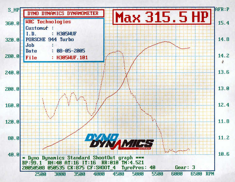
On Thursday 5th May, I took the car to the Weltmeister facilities at Silverstone circuit. A new Dyno Dynamics rolling road dynamometer has just been installed there - the most powerful in private hands in the UK.
Despite spending over 4 hours and nearly 100 runs, we (Chris at Weltmeister and myself) were unable to get a proper fuel curve. No matter what we did, we could not dial out a lean spot at around 4000 rpm or extreme richness above 5000 RPM. This seems to be a problem with the link computer as programming changes as broad as +/- 128 make no discernable difference. Also there seems a strange interpolation between fuel cells that mean a change to a particular area seem to have an unexpected effect on other areas of the fuel map. We had no facilities to make any timing adjustments with the equipment installed.
One thing we did confirm early on is that the PLX-250 wideband and Link analog/digital display were very accurate when compared against the state-of-the-art high speed analyser on the Dyno Dynamics - so any on road adjustment to the map were safe.
The following graph shows the AFR graph plotted at the 944 dyno shootout two days later on the same dynamometer.
I did find the problem with the low end running and lethargic response - a vacuum pipe that feeds from the inlet manifold to the pressure sensors, link MAP sensor and Blitz boost pressure sensor, had become partially crushed between a braided fuel hose and the clutch reservoir. The effect of this was to delay a proper vacuum signal reaching the sensors.
We had 2 other cars fitted with the GURU / Promax MAP setup. They also show fuel curves that are nowhere near flat and exhibit the same characteristic glitch around 4000 RPM as my car. Details at E409BKE and F640BWG
Comparing graphs from the Dyno, and a plot taken on the G-TECH RR on the way home on a clear flat stretch of road, show that the G-TECH is uncannily accurate to the Dyno plots. This also gives me faith that figures and plots on the G-TECH can be relied on as adequately accurate for tuning and comparison purposes.
The above graph was taken on 12th May 2005 after much more tweeking of the Link map on the road. This is subsequent to the Mapping session at weltmeister on 5th May. Using the 16% loss factor computed by the Dyno Dynamics dynamometer at Weltmeister a week previously, gives flywheel figures of approx 343 BHP / 324 lb/ft. This was taken at 18psi.
The fuelling is still way out with no way of getting rid of the big lean spot around 4000, or the over richness from about 5000. Changes to MAP zones 940-960 still seem to have no effect ! The overall power is CONSIDERABLY down on what was expected. I believe we should be able to resolve these issues when the car is remapped for fuelling and ignition when the Wolf-3D engine management system is installed.
As of 19/05/05 the link settings are
| Link Zone |
x00 |
x05 |
x10 |
x15 |
x20 |
x25 |
x30 |
x35 |
x40 |
x45 |
x50 |
x55 |
x60 |
x65 |
x70 |
x75 |
|
| 100 |
7 |
7 |
7 |
7 |
7 |
7 |
7 |
-3 |
-3 |
-3 |
-3 |
-3 |
-3 |
-3 |
-3 |
-3 |
|
| 200 |
-2 |
-5 |
-3 |
0 |
0 |
7 |
10 |
10 |
15 |
15 |
29 |
31 |
31 |
30 |
30 |
30 |
|
| 300 |
-6 |
-16 |
0 |
4 |
0 |
-2 |
1 |
-2 |
-6 |
3 |
-5 |
1 |
-4 |
-5 |
-5 |
-5 |
|
| 400 |
-1 |
-1 |
4 |
-10 |
0 |
-2 |
-12 |
4 |
5 |
-13 |
-12 |
-14 |
-5 |
-5 |
-5 |
-5 |
|
| 500 |
-5 |
-5 |
-5 |
0 |
6 |
-2 |
2 |
10 |
19 |
12 |
-8 |
16 |
0 |
17 |
0 |
0 |
0 psi |
| 600 |
-1 |
0 |
-6 |
-3 |
8 |
6 |
5 |
6 |
6 |
3 |
-7 |
-18 |
-15 |
0 |
0 |
0 |
3 psi |
| 700 |
0 |
0 |
0 |
0 |
-2 |
-11 |
3 |
8 |
40 |
30 |
14 |
10 |
-37 |
0 |
0 |
0 |
9 psi |
| 800 |
0 |
0 |
0 |
0 |
0 |
11 |
6 |
15 |
30 |
30 |
35 |
30 |
27 |
30 |
0 |
0 |
15 psi |
| 900 |
0 |
0 |
0 |
0 |
0 |
0 |
50 |
37 |
56 |
50 |
16 |
16 |
7 |
1 |
0 |
0 |
20 psi |
|
0 |
0 |
0 |
0 |
0 |
0 |
0 |
0 |
0 |
0 |
0 |
0 |
0 |
0 |
0 |
0 |
|
|
0 |
0 |
0 |
0 |
0 |
0 |
0 |
0 |
29 |
0 |
0 |
0 |
0 |
0 |
0 |
|
|
As can be seen, there is very little smooth transition across the values.
21/05/05 Bought a full car telephone kit for P910i mobile telephones for the forthcoming Scottish tour. The handset bracket mounts on the drivers side of the centre console with the phone positioned just below the HRW switch. It's a major job to mount more electronic modules in the passenger foot well with the DME, so I combined it with some other works.
I've been using the GURU v9 Link chips set to FQS 1, and not got around to changing it when I went from #55 to #72 injectors, instead just turning the master AFM fuel down on the Link programmer to compensate. With access to the the FQS switch on the DME, I thought it was time to change it to FQS 3 to better suit the injectors. On restarting the engine, the mixture was far too rich to run ! Backing the master AFM down allowed the car to run, but still FAR to rich. Reducing the value below -27% had no further effect. Time to check the fuel pressure in conjunction with some inspection work.
I wanted to remove the feed pipe to the Lindsey fuel rail to try an experiment. Since fitting the new fuel rail and using aeroquip hose throughout, I was getting a very loud injector pulse noise through the entire car as the pulses were amplified by the hard fuel lines underneath the car. I had lived with this for some time although I had a short (5") section of high pressure rubber pipe with swaged connections to insert with the feed line to absorb the pulses. Seemed like a good time to install the rubber hose to see if the pulse noise went away. The two unions on the fuel pipes where they protrude through the inner wings are different sizes - large for fuel feed (to the fuel rail) and smaller for fuel return (from the AFPR). Obviously it was the feed pipe that I wanted to modify, however the pipes that Dave Lindsey sent were for the smaller return pipe ! I thought I'd cobble up something to temporarily insert the rubber pipe for testing. It did indeed reduce the fuel pulses. I'll need a trip to Think Automitive this week to get a 90deg elbow and custom swaged pipe to carry out a proper installation.
When I depressurised the fuel rail, the pressure gauge stayed at 45 psi ! obviously the gauge had failed. Fortunately I had a new one ready to go on the 944S, so I fitted that. When the fuel rail was re-pressurised and the engine started, the gauge showed pressure to be about 30 psi with the vacuum disconnected. I had reduced the fuel pressure to minimum while on the roller at Weltmeister, but the gauge would not show less than 40 psi there. Obviously the gauge had been getting worse for a while. Dilemma - Car running far too rich with artificially low fuel pressure, although the GURU v9 FQS should have been for #72 injectors at 3 bar (43.5 psi) ! Turning the pressure up would obviously cause more problems.
I also noticed a trickle of petrol coming from the top of N0. 4 injector. This tired up with a faint whiff of petrol from inside the car during the last couple of hours engine running. The problem was traced to a bolt that holds the rear end of the fuel rail to the head having worked loose and reducing the clamping force of the fuel rail. This was tightened up, and the other bolt checked. Fuel leak is now cured !
While pondering the problem, I got around to another job. The brackets that hold the ABS sensor link plugs and KLR diagnostic socket to the inner wings had a lot of surface corrosion. I tool the brackets off and cleaned them up with wire wool. Zinc undercoat was applied, then a final layer of florescent green paint !
22/05/05 A bit of research of the old e-mails from Danno (GURU Racing) about my chips revealed that in map 2 in the chips, he had programmed a better strategy for a Kokeln club turbo and LR stage II intercooler. I decided to install the region coding link to select this alternate map. I also changed the FQS to position 7 - theoretically #72 injectors with 2 degrees retard. This solved the problem with FQS3 being FAR too rich to run. I reset the AFPR to 43.5 PSI at idle / no-vacuum. The car started and ran with idle stoic at Master AFM 5%. I now have enough control to lean the engine so much it stalls. This is much better and within the correct operating parameters.
With the engine running properly again, I was able to put the DME board back and start packing all the additional wiring and control boxes in the foot well area. This needs the glove box to be removed for full access. I also decided to hardwire a 4-way cigar lighter adaptor to feed the G-TECH and iPAQ PDA mounts on top of the dashboard. This leaves two spare sockets for temporary accessory expansion, plus regaining the original cigar lighter socket. I also hard wired in the Streetpilot car mount to get rid of a lot of extra and unnecessary cable lurking behind the dashboard.
Of immediate note, the G-Tech, which derives it's RPM sensing through it's power feed, is now much more stable, particularly at tickover. This is because of the much more direct method of connection. While the glove box was out, I checked all the heater control linkages and clips for correct operation and adjustment.
The interior is now back together but I'll have to wait till Wednesday to road test and probably start road re-maping the fuelling. On Wednesday, It's going up on the ramps for a full inspection, check for leaks, oil and filter change etc ready for the Scottish trip.
23/05/05 Road testing and tweaking the map settings begins. Although low row settings are still map-able, row 900 is remains uncontrollable. I'm going to turn the boost down to 11 psi so row 900 is never reached. Roll on the Wolf-3d ! (still no news ...)
25/05/05 A trip to Think Automotive produced a new -8 swaged end fitted to the length of high pressure rubber fuel pipe. The -8 end connects to the male -8 high pressure fuel feed pipe that enters the engine bay through the inner wing. The other end now connects to an elbow on the end of the Aeroquip pipe from the end of the fuel rail. Hope fully this will reduce the fuel pulses from being amplified to the whole bodywork via the hard sections under the car !
A trip to Northway tyres to get the front end aligned. We set the new adjustable plates to my preferred 1.5deg negative at the front. The camber, castor and toe-in were then adjusted as necessary.
Current settings are
Front
-1º41 Camber -1º42
+2º34 Caster 2º24
+0º05 Toe 0º05
Total toe 0º10 / Steer ahead 0º00
Rear
-1º50 Camber -1º42
+0º14 Toe + 0º20
Total toe 0º33 / Thrust angle -0º33
Currently front & rear M030 are still set to mid adjust.
27/05/2005 Visit to Motor Preparation for an oil and filter change, spanner test and general check-over prior to the Scottish Tour 2005 event for Porsche 944's.
27/06/2005 MOT passed at 119,278 miles.
01/07/2005 The Lindsey Racing engine management solution has arrived ! After an initial test, the existing Bosch DME and KLR computers were removed on their chassis. Next, the wiring loom for the Link map (Guru racing MAP-2) was removed from the factory loom. The narrow band feed to the DME plug was re-instated ready for the Lindsey Racing modules to be connected.
This consists of a new baseboard with the modules mounted on it. They are the Wolf-3D v4+ engine management computer, a complete standalone engine management solution (details HERE) to completely replace the Bosch DME, and the J&S Ultrasafeguard standalone knock control computer (details HERE) to replace the Bosch KLR. The Wolf-3D has been modified specifically to be plug compatible with the DME and use all the existing sensors, basically a plug & play solution. A custom loom extends to the J&S knock unit to allow direct connection of the original KLR multi-way plug, again using the existing knock sensor etc. The final component, a dual knock monitor HERE is currently on back-order.
19/08/2005 First dyno run with the Wolf-3D at Weltmeister. We found a very weak spot between 2500 and 3500 RPM. Did some basic work with the fuel map with the boost set to 16 psi. There is something in that RPM range that is causing the leanness that will not easily map out. After doing some bulk changes to the entire 2500-3500 rpm columns things were improving. We went back to the original map to look at the RPM range in context of the load rows being accessed, and also ran my slightly more aggressive timing map. After doing a power run to establish a base line to work from, the head gasket let go. Cylinder No.4 filled with water so we had to abort for the day.
09/2005 WUF is returned to Motorpreparation where the cylinder head is removed to reveal a failure of the Wide-fire head gasket at No.4 cylinder. A new gasket is fitted along with a complete engine flush / new plugs / service.
While the inlet manifold is removed, it is taken to CTM to have a hold drilled and tapped to mount a new air temperature sensor. The original air temperature sensor was mounted in the AFM. When the AFM was dispensed with and a map kit installed with revised intake, the air temp sensor was located in intake pipe just after the air filter. This is not a particularly good arrangement as it bears no resemblance to the temperature of the air in the inlet manifold - after it has been through the turbocharger. The new sensor is from a Cosworth and accurately sends the manifold air temperature to the Wolf-3d, where the signal can be processed to trim fuelling / timing etc in a much more useful way.
At the same time, a new injector wiring loom was custom built by Lindsey Racing to allow individual access to the fuel injectors. The standard 944 Turbo / DME arrangement uses banked injection - i.e. the fuel injectors are fired in pairs. This is much simpler in terms of wiring and sophistication of the DME to differentiate between which cylinder is actually firing. The Wolf-3D allows fully sequential injection, providing much more accurate metering of the fuel supplied to individual cylinders and the point in the firing cycle that it is injected. This allows lower emissions, more power and better fuel economy. Unfortunately, the standard 944 injector loom is 'siamised' whereby the banked injectors are wired together within the loom making the existing wiring unsuitable for sequential injection. Also, it known that the injection wiring and connectors can become a problem with a 944 as the car ages. The new custom loom was run from the engine bay, through the rubber 'snorkel' with the rest of the engine loom through to the passenger foot well ready for later connection of full sequential operation when a modified system of sync signals is available to the Wolf-3D.
31/10/05 WUF gets the first outing for a while with a visit to the Ace Cafe monthly Porsche meeting !
11/2005 with the temperature starting to fall, WUF is getting hard to start. This is traced to the water temperature sensor showing the water to be at 30 Celsius even when it's near freezing. The temperatures at the upper end look to be more accurately displayed. There is a calibration table within the Wolf for each temperature sensor, so it seems that the one for the Water temperature was wrong, whereas the air temp sensor seemed much closer to what was expected. The tables are accessed via the laptop link and fully programmable. Unfortunately, the Wolf stopped talking to the laptop.
During long discussions with Bob at RandomEMS, he indicated that development of the cam sensor kit for the 944/Wolf was near completion. As standard, the 944 / DME use two sensors on the flywheel to provide signals that the DME decoded to engine speed (RPM) and the reference point for TDC of cylinders 1&4 so that the DME can provide correct injection and ignition signals when required (programmed in to the map). Unfortunately, this does not include a phase sensor to enable the DME to know whish cylinder of a pair is firing and which is charging (4-stroke engine). The DME therefore fires both cylinder's injectors at the same time and the distributor (driven at half engine speed by the camshaft so always pointing at the appropriate cylinder) directs the spark to the correct cylinder.
The Wolf-3D has the ability to run fully sequential injection and ignition to provide much more accurate control of injection and ignition, therefore more power. The Wolf does, however, require additional timing signals to those provided by a simple plug-and-play solution in the 944 to enable these facilities. The new timing kit developed by AMS in Austraulia and Bob at RandomEMS (and soon to be available through Lindsey Racing) uses a new sensor disc driven by the camshaft to provide the necessary timing and phase signals to the Wolf-3D to allow full implementation of sequential injection.
During the early part of December, the Wolf-3D died totally. A decision was made, in conjunction with Lindsey Racing and RandomEMS that I would wait for the cam sensor kit and a replacement version of the Wolf-3d with additional processing and firmware to allow interface of the new type hall sensor used in the cam timing kit. WUF was put away awaiting the next parts shipment !
03/01/2006 I unpacked the parcel from Random EMS and began the upgrade to the cam trigger sensor assembly. The complete kit consists the cam sensor and attached cable, a grommet for the cam cover, 3 rivets, a drilling template, a 3-pin connector plug to connect to the speed sensor connector at the rear of the engine and the chopper disc. The chopper wheel mounts between the cam wheel and the rotor arm assembly. This is sensed by a hall sensor that is riveted to a right-angle bracket that is in-turn mounted inside he cam gear cover. A cable runs out through the grommet, parallel with the fuel rail and a 3-pin plug connects to the 3-pin speed sensor connector, having first removed the original speed sensor plug.
Firstly the intercooler pipe, MSD assembly, King lead, distributor cap were removed. 4 bolts holding the plastic timing gear cover were then removed allowing access to the two lower bolts for the Cam wheel cover. This cover is removed after the final top bolt is removed. Next, remove the rotor arm assembly by means of a 8mm spanner to remove the retaining bolt. Finally, the splined bolt in the end of the cam is removed to allow the old gear retaining collar to be removed.
With everything clear the new parts are fitted. the chopper disc assembly replaces the gear retaining assembly. This is slid on the end of the cam end engaged in the keyway, finally being secured in place with the spline bolt in the end of the cam. Next is to modify the cam wheel cover. This was cleaned out and the supplied template aligned and 3 holes marked with an automatic centre punch ready for drilling. These were drilled out to 1/8" and the 3 supplied rivets installed to check alignment of the hall sensor bracket prior to final assembly. With everything looking good, the template was used to drill the final hole for the cable entry grommet. Lastly, a Dremmel with a sanding disc was used to smooth the date casting where the base of the sensor will mount to ensure everything is flush mounted.
The grommet was slid over the connection cable (with the aid of some WD40) and the cable fed out through the hole in the casting. The hall sensor plate was located and secured with the 3 rivets. Finally the grommet was fitted in place and the internal cable routing finalised. At the far end of the cable, the supplied 3 pin Bosch plug was fitted ready to connect to the 944 engine loom speed sensor connector. The cam cover was now complete and ready for refitting. The cover was offered in to place the the engine rotated by means of the crank bolt so that the chopper disc would allow the hall sensor to slide through. The cover was pushed back towards the mounting surface, but something was stopping it ... After a lot of inspection it was discovered to be the sensor bracket contacting the 4 spline bolts in the Lindsey Racing adjustable vernier cam wheel ! This had not been anticipated on the original kit as this had been developed with the standard Porsche cam gear which is much thinner and shallower. After a lot of examination to ascertain the exact problem, an air cutter was used to make course adjustments to the alloy sensor bracket by taking off the corners. This was then finished off with the Dremmel and hand filing until there was clearance all round the sensor assembly. This was ascertained by several trial fittings of the cam cover and rotating the chopper disk by the crank bolt and finally by starter motor to ensure full clearance within the cam wheel cover assembly.
With the new cam sensor assembly in place, the sensor cable was loose run parallel with the fuel rail. The speed sensor (lower of the two rear plugs) was separated and the new sensor connector mated to the wiring loom to send the new cam sensor signals through the existing DME loom to the Wolf-3D. Finally, the 12v feed wire to the hall sensor was temporarily connected to the 12v post on the bulkhead.
Next the modified Wolf-3d (modified internally to accept the hall sensor signals from the cam sensor rather than the speed and timing sensor signals from the flywheel sensors) was unpacked and installed on to the bas board with the J&S safeguard. Finally the jumpers on the 20-pin auxiliary connect were changed for the (soon to be replaced) banked injector configuration and the whole assembly installed in the passenger footwell so that the diagnostic led's on the Wolf & J&S were visible. Making sure the engine bay was clear of tools, the engine was turned over on the starter motor to check the timing signals by means of the diagnostic led's on the Wolf and the hand controller. After a couple of revolutions, all the diagnostic led's were looking good. The final step was to secure the plastic timing cover, reinstall the rotor arm assembly, distributor cap, MSD control unit and the intercooler pipe.
The engine started on the second revolution ! After running for about a minute the Link AFR was showing very rich running. The map in the (new) Wolf-3D was for #55 injectors, so this was to be expected. I used the hand .controller to tale another 20% of fuel out and the tick over stabilised. With the car now mobile, I decided to jet wash / steam clean it where it had been covered in winter road filth for the last few weeks while it had been stranded in the garage.
After this the car was started and left to idle for about 90 minutes while I washed the other cars. The Idle was rock solid at just over 1,000RPM for this duration and showed no signs of stumble or misfire, in fact the best it had been for some time. Unfortunately as I got in the car to reverse it in to the garage, the engine died. Trying to re-start it bought about a bit of splutter but it would not run. The diagnostic led's on the Wolf confirmed loss of trigger signal from the new assembly. With the light gone and falling temperatures I got the car back in the garage for the night. A telephone call to Bob at RandomEMS suggested that it may be a similar problem to one he had had whereby the sensor cable had fractured either inside the cam wheel cover, or within the heat-shrink assembly where the sensor wires were connected to the main multi-way cable.
04/01/2006 The engine front of the engine was stripped to allow the cam wheel cover complete with sensor assembly to be removed (remembering to rotate the engine via the crank bolt to allow the sensor to move out between the gaps in the shopper disc) A set of continuity tests with the fluke Scope meter showed an open connection between the 3-pin plug and the trigger out signal from the sensor itself. After a lot of stripping back of insulation, the break was found in the sensor wire between the internal 'p' clip and the heatshrink for the cable join.
Having decided that this entire cable assembly was a bit fragile, especially at low temperature where the stiff multi-core cable supplied would be transmitting vibration in to the join within the cam gear cover, I decided to look at isolating this vibration by using a solid connector to terminate the hall sensor cable within the cam wheel cover. O ordered a set of 'Lemo' 3-pin connectors. These are push-fit very high quality connectors that are designed to be used in a harsh environment.
07/01/2006 The Lemo connectors arrived so it was time to fettle the hole previously occupied by the cable grommet to fit the Lemo 3-pin socket. This was connected to the 3 hall sensor wires by means of some diode leads to extend from the socket. The socket and wiring were then sealed with epoxy resin to prevent any internal vibration weakening the connections and allowed to harden overnight. A new cable was made up to go between the cam cover socket and the speed sensor connector at the rear of the engine. Rather than reuse the original supplied cable which seemed to be very stiff particularly when cold, a new type of cable was used. This is 4.8mm outside diameter and features a screened coaxial core and four unscreened cores. The screened core was used for trigger out signal. One end was assembled in to a 3-pin Lemo connector, and the other to the original 3-pin loom adaptor plug.
08/01/2006 Attempted to fit the modified cam timing gear cover but struck another problem - the newly installed 3-pin socket is trying to occupy the same space as the edge of the vernier cam timing gear. After a lot of trial end error, the 3 pin socket was ground down (it could not be removed because it had been epoxy-resined in place) so as not to interfere with the vernier gear and a new location for the socket was sought. This was repositioned on the outside edge of the cover, outside of the vernier gear and timing belt circumference. After a successful trial fitting of the socket, a new mini loom was made up to link the socket to the tails of the hall sensor. After a trial fitting of the complete assembly, and turning the engine over on the started to make sure there was no interference contact anywhere, the cover was bolted back in to place, rotor arm and distributor cap refitted, along with the MSD unit and Intercooler pipe.
09/01/2006 Collected the Bosch connectors. Fitted a two pin connector directly on to the end of the AFM loom for direct connection to the new air temp sensor.
12/01/2006 The sparkplugs were cleaned and the fuel starting pulse duration changes from 3mS to 9mS and WUF burst in to life ! Next job was to tidy some of the new wiring. The old injector loom was cur back and sealed with heat shrink sleeving. The loom from the cam sensor was trimmed back to length at the bulkhead end and a new Bosch 3-pin connector fitted along with an insulated spade connector for for +12v feed for the hall sensor. After running WUF for an hour, time for a road test and to get some petrol. 10 miles and an hour showed no problems. The water temp calibration table is still out so a full calibration of both water and air temp sensors in now imminent, more details will follow.
13/01/2006. The temp sensors are now calibrated. This done while still connected to the engine loom by immersing them in a small metal can, along with a calibrated thermocouple, and heated to beyond boiling point with a paint stripper heat gun. As the water cooled back to 6 degrees Celsius, the calibration tables were tweeked in. Values above 105 and below 6 degrees were extrapolated. A wiring loom for the sequential injection, and final power feed for the cam sensor supply were also run through the bulkhead. Bothe the 4 'coil on plug' and the 4 coil pack should be here next week so testing can begin.
The coil-on-plug parts should arrive during the week. J&S are supplying a 4-channel version of the UltraSafeGuard and dual knock Monitor via Bob at RandomEMS so should be another couple of weeks before I can finally get the fully sequential modifications completed and start the next round of tuning ...
14/01/06 Cold start settings are now being tweeked - starting injector pulse duration, target enrichment and idle speeds during warm up phase etc. I decided to put the electronics modules and interior back in so WUF is driveable again. I've now driven 30 miles while working on the low speed (<3,000RPM) fuel map for driveability. It's nice to be back on the road again !!
15/01/06 Fitted a new set of plugs and done further tweeking on the new fuel map. The engine is now idling so smoothly at 875RPM that you could stand a 50p piece on end on the top of it - BMW straight-6 smoothness. Went for a 100 mile round trip and mid-range fuelling is now very good started working on the high ranges. Unfortunately, ending with plumes of smoke - looks like another wide-fire head gasket gone. Now confirmed - No.4 filling with water ....
30/01/2006 The old widefire gasket had gone in the same spot - cylinder#4 had blown out. A new Cometic multi-layer metal head gasket was fitted. The coolant and oil systems were thoroughly flushed and refilled with new antifreeze / Magnetec and filter. While the car was on the 4-poster, a timing sync issue was resolved with Bob at Random EMS that had been masking an overall timing issue that possibly led to the most recent head gasket failure. The overall timing reference is now spot on and injector pulse sync has been corrected. With the new timing reference, the whole low load remapping begins again !
05/02/2006 Below is a G-Tech plot of a 2nd gear pull in 2nd gear at 17 PSI. Things are heading in the right direction now. Fuelling is a lot better and it's nearly time to start on the timing map.
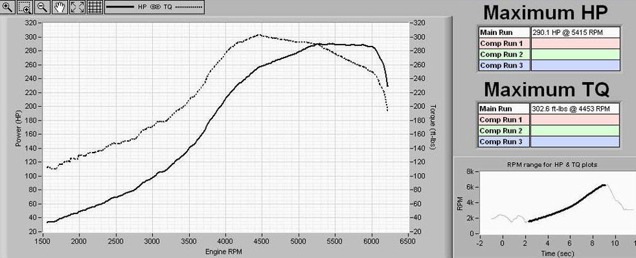
We had a bit of a get together and I took some exhaust noise figures. These were taken with a noise meter placed 1 metre from the exhaust, offset to the side at an angle of 45 degrees, and with DIN 'A' noise weighting. First figure is at idle, second at 3,000 rpm with no load.
924S with standard exhaust 73 / 80 dB
944T with ESS 6x4 rear box 76 / 85 dB
944T with 4" rear exhaust 74 / 85 dB
944T WUF straight through exhaust 94 / 105 dB
Obviously when the cars are under load and at 6,000 RPM ....
07/02/2006 After discussion with Bob Boyer, I started work on the ignition map which is currently extremely conservative. For now the intention was to lower the EGT on cruise from 1550 to nearer 1400. This was accomplished by the addition of some more low / mid load ignition advance. The real work won't begin until the new J&S / MSD / coil-on-plug setup is installed alongside the J&S knock monitor gauge.
08/02/2006 One of the advantages of a clean engine bay is that you can usually spot quite quickly when something is amiss. My cam tower becoming very dirty near cylinder #4 prompted an examination which showed that the rubber cap that seals the exhaust sniffer tube had split in a big way and was dumping exhaust straight on to the cam cover. It is possible that this had begun to split some time earlier but the higher boost levels had finally split it apart. A new factory replacement is now fitted and this may speed spoolup. When the car is next on the ramp, I'll remove the sniffer pipe completely and seal the port on the x-over pipe. There is no current requirement for this pipe.
My drivers side wiper decided to give up the ghost. The usual problem - the linkage started popping out indicating that it was worn. To replace this it is easier to remove the complete wiper assembly, which also requires the removal of the heater airbox. This was done and the opportunity taken to vacuum out all the winter leaf debris. One of the vacuum pipes that operated the recirculate flap valved was perishing at the end where it fits over the actuator valve, so the pipe was cut back to a clean section. This will all be replaced with purosil pipe soon to help retain vacuum integrity.
13/02/2006 Went to Silverstone to see some 944's enjoying a track day. Decided to drop in to Weltmeister and do a power run and look at the AFR curve. Fuelling is a lot better now, but really need to get on with mapping the high RPM stuff and make a start on the ignition map when the coil-on-plug goes on. 17 PSI runs were totally consistent, but trying to run higher boos had unpredictable results as the boost control was all over the place. Looks like a temperamental wastegate.
23/02/2006 A trip to Turbo Dynamics in Christchurch produced a Tial F46 wastegate with .8 bar spring to replace the Lindsey Racing DPW that is suspected faulty and leading to the eratic boost control. Having had doubts about the performance of the Bailey DV20 dump valve in the past, I took the opportunity to get a replacement in the form of the Tial 50mm BOV which comes highly recommended. This is a well engineered and substantial piece of engineering that comes with a flange that needs to be welded directly in to the hard pipe for maximum air flow.
24/02/2006 Went to Motorpreparation to install the Tial F46 wastegate. WUF was already fitted with a Lindsey Racing Dual Port Wastegate and was dumping to atmosphere. However, I was still experiencing the random boost problem so decided to remove the wastegate from the equation in case it had a sticking valve. For a dump to atmosphere application, fitting the Tail was quite easy as there was no connection back in to the exhaust system.. The orientation is the opposite way round from a standard factory (or Lindesy Racing DPW) wastegate in that the exhaust gasses enter the bottom of the wastegate and exit the side port.
The inlet flange on the Tial F46 already has the correct 4 bolt pattern to directly mate up to the pipe that connects to the 944's crossover pipe. This is a much better arrangement than using the 38mm version of the Tial which requires adaptor plates that are renowned for loosening if they are not welded on. Loctite was used on the bolt threads and they were then torqued up to fix the Tial to the pipe. The heads of the bolts were then drilled and wired to prevent them from loosening. Once the Tial was prepared for fitting, the banjo connectors were installed in to the two existing Aeroquip pipes that lead up to the Blitz SBC-iD dual solenoid boost controller. Next, to make more room for the Tial, the bracket that bolts around the torque tube and provides extra support for the standard wastegate was removed. Once this was done, the banjo connectors were screwed in to the chamber of the Tial, which was then lifted in to position and aligned centrally in the available space.
With the Tial wastegate installed in to final position it was time to fabricate a new dump to atmosphere pipe. The flange provided with the F46 kit determined the diameter of the pipe required and a trip to the local exhaust centre produced a back box assembly that had a suitable diameter with the necessary bend required to fit in the space available. This pipe was cut off with an angle grinder and after a trial fitting, was squared off ready to be welded to the Tial flange plate on one end, and slash cut at the other (venting) end. This was then welded by Michael at M&Y and finally installed with Loctite on the bolts and a gasket.
First road tests and adjustment of the gain control on the SBC-iD show that boost is now much more under control and a 19PSI run seemed stable.
The next step will be to get the new Tial 50mm blow off valve installed. This will require a new hard pipe between the intercooler and throttle body and a 'special' is being prepared at Lindsey Racing .... After drawing a complete bland on obtaining the correct new connectors for the Denso coil-on-plug ignitors, I found a breaker who sold m a complete loom for £20 !
04/03/2006 started testing the coil on plug ignition on the bench. The Suzuki loom was stripped and the 4 connectors with pigtails were isolated. These were connected to the MSD DIS-4, and in turn a car battery. The wiring was checked and test firings produced an incredibly 'fat' spark on an old sparkplug. with the earth 'finger' removed, the system would maintain a spark from the centre electrode all round the edge of the plug. An HV probe and Fluke scope meter confirmed 40 KV !
With the testing done, I set about making the loom between the 4 coils and the MSD unit which will be mounted at the front of the engine in place of the existing single channel MSD-6T unit. The loom features high temperature glass reinforced braiding to reach the highest standards. All the wiring for the coils and MSD are now ready and waiting for the 4-channel J&S Ultra Safeguard knock control - on it's way over at the moment !
10/03/2006 Did some stress testing of the MSD / Coil combination on the bench, the result of which was seeing some slight arcing within the connectors, so these were replaced with up-rated types with 9A contacts and greater distance between adjacent pins to better insulate the 480v that fires the actual coils. The sparks produced are quite spectacular. See http://www.cannell.co.uk/video/MSD_sparkplug.avi
11/03/2006 I did my first G-Tech run on the 'standard test road' since swapping the LR DPW for the Tial 46mm. All parameters were as set when the car was run at Weltmeister on 13th February.
All runs were at 17PSI. We did do a run at 18PSI, which showed power was increasing at about 17BHP/PSI with the LRDPW.
Weltmeister showed 290/270 RWHP/TQ (342.5/321 FWHP/TQ). With the new wastegate, G-Tech reads 308.1/337.8 RWHP/TQ (362/397 FWHP/TQ). The graph below shows today's run (11/03/06) in black vs a run from (05/02/06) in red. Again still at 17PSI.
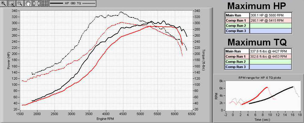
16/03/2006 The deliveries from Lindsey racing, Random EMS and Demon Tweaks arrived. LR have made me a custom pipe between the throttle body and intercooler. This does not have the standard take off pipe for the blow off valve. It has the throttle body end flared out to match the 76mm throttle body allowing a straight coupling to be used and reduced airflow turbulence at that junction.
The pipe was then further modified by Jim at CTM to add the huge bung for the Tial 50mm BOV in the opposite side of the pipe to the standard BOV. He also welded in a bung for the sensor that monitors the air temperature coming out of the intercooler, also a corresponding bung in to the turbo - intercooler pipe for the intercooler inlet air temp sensor, finally welding up the redundant holes in the turbo - air filter 'J' pipe that are no longer needed for the intake air temp sensor and vapour purge pipe. The pipes were then sand blasted and have been power coated in red to match the inlet manifold and cam tower. There are also new laminated silicone connecting hoses and 'Mikalor / ABA' constant torque hose clamps ready to be fitted.
As suspected, the Bailey DV24 blow off valve was holding no vacuum and is the probable cause of the unstable vacuum at idle and potentially a large boost leak.
The 4-channel J&S is now here, the last part in the coil on plug puzzle so after some baseline dyno pulls I should be able to install the cop setup and get some real comparative figures before moving on to the next, more serious, tuning stage. This will involve putting the big valve head back on. The head is currently back at CTM to have the Lindsey Racing steam vent kit properly machined in and to skim the head to bring the compression ratio back up.
17/03/2006 The charge air temperature sensors were cleaned up and new wiring loom created before being installed back in to the new hard pipes. the Tial 50mm blow off valve was also installed and all pipes reinstalled with new hoses and clamps. A trip to the Weltmeister dyno to do some base runs to do a before & after with the coil on plug ignition had to be cut short because a heater hose sprung a pin size leak !
There is still a problem with the boost curve even after the Tial was fitted. This needs the Blitz SBC-iD to be substituted out as the next test. Best figures of the day were 374/346 FWHP/TQ at 18PSI.
18/03/2006 Coil on plug project day ! first the turbo-intercooler hard pipe was removed to give access. Next the original plug leads and plugs were removed. The plugs were cleaned up and re-gapped at 0.030". Then the terminals were unscrewed from the top so that they will fit in the Suzuki cop's. The original Porsche spark plug cables (BERU) had the sealing caps removed from the ends and these were then refitted on to the cop's to provide the same sealing in to the spark plug cavities in the 951 head. The cop's were then installed and the cop sub-loom connected.
The original single channel MSD unit and custom bracket were then removed and separated. The new 4-channel MSD unit and bracket were the drilled to allow best fit in the engine bay, then the assembly was bolted back in. The original spark plug cables and MSD blaster coil were then removed. The main power (engine bay) was then made up and connected, likewise the three additional looms (signal, control and new knock sensor) were made up and run through the 'snorkel' in to the passenger compartment ready to be terminated.
Finally the original single channel J&S was removed and the base plate drilled to accept the custom 4-channel unit. Finally, new looms were made up between the J&S - Wolf-3D and ignition signals to the MSD in the engine bay.
19/03/2006 Finished the passenger compartment wiring looms and has engine running on new cop setup. Took the cop units out and cut them down slightly to provide better fit and more clearance above, particularly for cylinder #1 where the banjo bolt on the turbo-intercooler hard pipe was touching.
23/03/2006 A delivery from Lancaster's, so back down to the garage. I managed to change the split water pipe without removing the inlet manifold - just ! The system was bled with the front of the car pointing sharply uphill !
With the help of Bob Boyer on the telephone we resolved the bug in the coil-on-plug ignition, which turned out to be the coil sequencing information in the Wolf. With that resolved it's all running properly ! The tick over has moved on to a level of smoothness. I'll do a road test tomorrow before putting all the electronics back in the passenger foot well (nearly an hour's work !)
I have ordered an #11 spring for the Tial BOV from Turbo Dynamics as WUF produces so much vacuum at idle that the BOV is staying open with the spring as supplied ! This should arrive in the next day or so.
25/03/2006 The ECU board was finished and the HKS Camp piggybacked on the the J&S to make the most of the available space in the foot well. All the electronics modules were put back in place and the engine started ! The replacement spring arrived for the Tial BOV. To change this, I rotated the hard pipe enough to get to all 6 Allen screws on the BOV. The top then came off and it was a simple matter to swap the spring. These have very high poundage so a lot of effort was needed to put it back together ! With the car hot and idling, the BOV is just under the threshold of opening. Idle air now flows through the entire intake rather than just the BOV ! The plastic trim below the windshield that is designed to keep rain water out of the heater assembly had turned brittle with age and had consequently cracked during the many times it had been removed over the years, so a replacement was provided by Colchester OPC and has now been fitted.
With the cop setup having run for over 2 hours without any problems it was time for the first road test. This ended up as an 85 mile trip up the motorway and back. Unfortunately it was raining hard and the motorway was fairly busy with road works so no full power runs were possible. I found a glitch at 1,750 RPM where power would appear to die under high load. Changing the enable speed for the J&S from 1,750 to 2,000 RPM in the Wolf-3D software seems to have solved the problem.
First tests show that there are absolutely no signs of any sort of missing at all throughout the rev range. The car can be run to the rev limit (6,800 RPM) in second gear under load without any sort of glitch. The engine revs much more freely and responsively, returning to a stable smooth idle at 850 RPM.
I had 6 miles of 40 MPH speed limit on the motorway with gentle and steep gradients. What is immediately obvious is that the car is perfectly happy to lumber along at 33 MPH in 5th gear at around 1,200 RPM, and pull cleanly from those revs ! I was able to add a lot more advance and the power felt significantly stronger and smoother at low RPM. I was also able to loose up to 200 degrees of EGT ! By the end of the motorway section, I had made significant changes in the timing up to the 2,500 RPM band. Overall, it significantly better throughout the complete rev range. The next trip to Weltmeister will let me reload the original maps and so a comparison to the original ignition system before further tuning ! Currently the plugs are Champion RN7YCC gaped at 30 thou.
06/04/2006 A new Bosch wide-band sensor was fitted as the old one was starting to give erratic readings on the Link AFR gauge.
12/04/2006 Finally a trip up to Weltmeister to dyno test the new coil on plug setup. It was not possible to do an exact before and after comparison because other changes had occurred to the engine spec since the last run with the distributor ignition. There is still a major problem with boost control, which currently leaves the Blitz boost control solenoid pack suspect and the next thing to replace. Even so, power rose from 374 to 403.7 BHP (29.7 BHP / 8%) and torque from 346 to 360 lb/ft (14 lb/ft / 4%). Once the boost control problem is sorted, it should be OK to map to 23PSI, the limit of the Wolf-3D's internal MAP sensor, before refitting the big valve head.
21/04/2006 I managed to obtain some special sparkplugs to try - NGK B10EV. These are the coldest I can find and I need to test them with the new ignition setup. If they do run OK, EGT should drop further and I may be able to slightly increase the timing.
27/04/2006 The new plugs were installed and WUF taken to Weltmeister to see how they perform. The answer is being able to increase power from 374 to 404 BHP with slight tweeking of the map. The new ignition system is now proven to everything it was designed to do. We didn't carry out further mapping because the boost control is still too unstable. A long discussion of the days results with Bob Boyer at Random EMS bough forth the design of a unique boost control setup run from the Wolf-3D.
03/05/2006 A trip around the south coast to collect the various components needed to prototype the boost controller which was then assembled ready for test
05/05/2006 A trip to Weltmeister for some dyno pulls show that the boost control works well - programmable in 125RPM increments. There was no sign of spike or over boost. We did some runs as low as 12PSI but ran out of time to accurately set 20 PSI and start mapping.
16/05/2006 New windscreen fitted by Autoglass.
24/05/2006 New rear tyres fitted. EBC Red pads fitted all round.
22/06/2006 Passed MOT with 127,376 Miles. Fitted new anti-squeal pads to the front calipers. Reset 4 wheel alignment. Replaced broken handbrake spring on O/S.
27/06/2006 Replaced the original front 225 tyres with 245/40/18 ZR Pirelli Rosso.
08/08/2006 Replaced rear wheel bearings. Change gearbox / diff oil with new Swepco. 128,860 miles.
27/11/2006 Replaced the failed battery. Another HCB096!
Braking is much improved in stopping power and feel after the fitting of new drilled discs and pads. It now feels as if it really will stop properly, although fade is still apparent if pushed.
The MOMO wheel came off the RS500 and I have fitted a snap-off adaptor as in the 944 Turbo. This lets you take the steering wheel off very quickly to helps when cleaning the inside and also as an additional anti-theft deterrent.
The timing chain tensioner change has quietened things up a lot on the top end. It is booked in with Peter Philips at Motorpreparation soon for a change of timing belts (last changes 2 years ago) and the timing chain. At the same time the idle speed control valve will be stripped and cleaned (inlet manifold needs to be removed to access it) to solve the erratic idle speed when warming up. After much discussion on the Titanic forum, I have decided that the Thermostat and water pump will also be changed.
I finally got round to replacing the broken drivers door mirror and door stay that I got from Porsche-apart with the M030 suspension.
On 7th June 2003, The MOT passed with a clean bill of health.
14th November. Minor service carried out by Peter Philips at Motorpreparation. Oil and filter change (Magnatec). Checked & tightened rear hubs.
The carpet in the boot was getting wet due to a leaking rear hatch seal. Seal was changed. The Battery decided to go flat overnight. This turned out to be the radiator fan thermo switch going short circuit. This was replaced and the cooling system bled. As a precaution, I replaced the battery with a Halfords Calcium, as in the Turbo.
08/02/04. First works of 2004 ! The rear tyres were getting very low on tread (recent snow & Ice was interesting ! I finished off any remaining tread in an ice filled car park) so I decided to use the wheels that I had removed from the Turbo last year to make way for the 18's. A thorough steam cleaning of the engine bay and underneath including wheel arches has confirmed a broken OSF anti-roll bar drop link to be the cause of front suspension clunking. Probably broken as a result of the 36 speed humps on the way home every day ! Replacement to be ordered ASAP. I fitted a replacement radio because of bad local interference on some FM frequencies by a pirate radio station. I chose a cheap DAB tuner that also has AM/FM CD. It's 20W RMS per channel and works well with the up-rated speakers. Last year I bought a spare instrument cluster at Husbourne Jumble sale. This was from a Lux model with the optional economizer fuel consumption gauge. This had now been transferred to my 944S instrument cluster ands worked immediately from DME signals in the loom.
14/02/04. Replaced the OSF anti-rollbar drop link and bushes. Replaced the NTCII sensor for the DME. Tried some Wyns Hydraulic Lifter treatment to quieten the hydraulic tappets. Seems to work very well, much reducing the noise in the first couple of minutes on a cold engine. Also tried Wyns dry fuel to get any moisture out of the fuel tank.
28/09/2004. The 944S has been off the road for some time at Motorpreparation while extensive maintenance work is carried out. The gearbox, which was noisy, has been replaced with one obtained secondhand over a year ago from a member of the titanic 944 list. This was stripped and checked / refurbished by Target Transmissions in Edgeware. This has been fitted with a new quick-shift mechanism and Swepco (blue) oil.
The front brake calipers from my 944 Turbo/250 (928S4 specification) are being refurbished and painted and fitted to the front with the aid of Kokeln Racing radial mount brackets, supplied by Lindsey Racing. The cross-drilled discs will remain and probably Green-Stuff pads will be fitted. At the rear, I am currently sourcing a set of 944 Turbo (952) rear callipers to work with the existing cross-drilled rear discs. I have a set of stainless steel braided brake lines to fit as well and brake fluid will probably be ATE super blue.
The engine has had a new water pump and thermostat, cam chain, belts and all (5) rollers replaced. A new knock sensor has also been fitted. Lindsey Racing have supplied an adjustable fuel pressure regulator and fuel rail pressure gauge to allow a degree of tuning flexibility in conjunction with a propose re-map of the ECU. A full major service has also been carried out.
When the car's back together it will go to Jamsport for some dyno testing. It is proposed to take figures with the standard chip, blitz chip and Promax chip. The exhaust will then be swapped for an ESS rear section and the tests run again. Finally, an ESS induction kit will be added and the tests run a third time.
Which ever chip produces the best results will then be fine tuned with the adjustable fuel pressure regulator to get maximum benefit. These power graphs can then be directly compared and contrasted with the figures obtained for a range of 944 cars during the Jamsport dyno shoot out earlier in the year.
I have also obtained a set of track-day wheels from Simon Butterworth (Porsche-Apart) at the recent Husborne Crawley Porsche auto-jumble. These are 17" x 7.5" & 9", currently fitted with Michelin Pilot SX tyres. The design 90's will be kept for road use and sprayed white, retaining the Continental's.
The majority of engine servicing work is now complete. New water pump / thermostat / timing belt & roller kit, cam chain and tensioner. Just the inlet manifold to remove now to replace the knock sensor and some rubber piping.
18/03/05 The car is currently in Streamline for bodywork and a respray.
Rebuilding the turbo callipers has now begun. The calliper bodies are now back and powder coated. They just need a final clean up and detailing of the Porsche logo before the new pistons and seals are fitted.
26/04/05 The car has been sprayed and is in the bake oven. The new exhaust has arrived from Essential Styling
29/04/05 The paintwork is being prepped ready for the car to be reassembled
07/07/05 The full respray is now complete. The car is now being put back together.
13/07/05 The rear calipers have been reassembled and mounted to the rear hubs. Unfortunately further suspension / brake works stop when it is found that Porsche have provided wrong piston and seal kits for the front callipers. Twice. We try a quick mock up of the front callipers / radial mounts which goes OK, but the radial mounts will not fit the 944S hubs ! A call to Dave Lindsey confirms we need to change to turbo 220 hubs if we want to use the radial mounts.
Turbo/250 hubs are not available second hand at the moment (Porsche order factory parts would cost nearly £4,000). Fortunately John Sims has a set of turbo/220 front hubs available since he changed his to turbo/250's to fit 928S4 callipers.
We decide to fit the replacement induction and exhaust at this stage in preparation for the Dyno session at Weltmeister. The induction change consists of a K&N cone air filter mounted directly on to the AFM, with the standard box and piping being removed. The entire rear exhaust section is replaced with one from ESS (Essential Styling) developed in conjunction with Janspeed. This is stainless steel and features twin 3" outlets.
15/07/05 One of the knock sensors is known to be cracked, so it's time to remove the inlet manifold to get access. It turns out that both sensors are cracked / damaged due to heat over the years, so both are replaced with new items. The wiring on one look a bit suspect near the connector plug, but a continuity check seems OK. While the inlet manifold is off I can carry out a venturi delete conversion. This involves removing the Y shaped pipe section comprising part of the brake servo / idle speed control valve circuit. This is replaced by a single Purosil hose section between the servo and inlet manifold and a reroute of the idle circuit. The upshot of this should be better braking feel and idling, with the removal of another potential source of vacuum leaks.
16/07/05 A morning visit to Porsche at Reading produces more calliper pistons, solid crossover pipes, clear stone chip guards for the arches. Euro Car Parts supply a new pair of drilled front Turbo/250 front discs. John Sims joins us at Motor Preparation with his spare pair of Turbo/220 hubs. The hubs are re-greased and installed. I finally have the correct piston kits for the front calliper and Pete assembled the first one. Problem. We do a trial fit up and the Kokeln radial mount brackets are wrong !
With no other options and the Silverstone track day just two days away we decide that the only option is to refit all the original hubs and brakes ! This at least goes to plan.
Time to fit the track day 17" wheels. Rears go on no problem. The fronts won't. It seems that the hub centre / grease cap of the 944S is too big for the centre of the Boxster derived rims. Final result at 9PM is a car with the original brakes, 16" road wheels and tyres, no ABS and very suspect front geometry.
17/07/05 I collected the 944S from Pete so I could give it a good wash and some minimal road miles before tomorrows track day. No sign of a cure for the ABS fault. Car's pulling slightly to the left and there is a large difference between the front cambers - n/s is positive, o/s is optimistically negative ! Should all combine to add to the track experience ! I did some work in the idle, but connecting the idle speed control valve still causes a lot of hunting, despite power resetting the DME (which has adaptive idle function). The idle speed control valve is disconnected again and a warm base idle set manually with the throttle stop screw. Finally the car gets a thorough wash and steam clean inside and out. A wiring fault in the door sees the mirror switch disappear inside when the electric window is lowered and raised ! The door is partially stripped and the cable correctly routed.
18/07/05 The day begins with a final fluid level and tyre pressure check. We start to fit the white stripes, but run out of time to complete the job. With cameras onboard I set off for Weltmeister and Silverstone. The journey goes well and when I arrive at Weltmeister I remove the DME for easy access to the chip ready for the Dyno. Refitting the DME, the car won't start. The fault is traced to the bad cat 2 alarm / immobiliser installed in the passenger foot well. The remote alarm is dead so the DME signals are isolated. With time starting to run out, I bypass the immobiliser circuits, which brings the car back to life. The drivers door glass decides to come out of it's runner, so leaving a 1" gap at the top when trying to close it. At last ventilation won't be a problem on the circuit - I just hope it doesn't rain again !
Chris Davies got the car strapped to the dyno ready for a first pull with standard chip. A 944S is rated at 188 BHP in standard form. Mine is now fitted with a K&N cone air filter mounted directly on the AFM and an ESS dual 3" exit read exhaust section. I'm thinking that these should more than compensate for any loss of power over the car's nearly 123,000 mile life. Wrong. The most it will manage is 154.3 BHP / 145 LbFt. Something obviously not quite right but no time to investigate. I swap the DME chip to the Blitz one and we immediately run again as John Sims has now arrived and is ready to do a run in his Turbo that has been tuned by Thor racing 2 days previously. The chip does indeed raise the power to 171.9 BHP / 156 LbFt. The car is removed from the Dyno bay and I refit the DME ready for the track day. The power loss needs investigation. My initial reaction is that the fuel curve is not bad, although there is plenty of room for further improvement, so most likely cause is the knock protection in the DME holding timing back. Unfortunately, the 944S DME faults can only be read by a special Bosch analyser that is not available on the day.
So to the track itself. The first session went well, approximately 40 minutes. While the car was idling in the pit garage to cool down, tick over had increased to about 1,500 rpm. The car was pulling to the left under power and also not the most stable under braking. Power deliver, although low, was very smooth all the way up to the 6,800 rpm rev limit that I kept hitting ! A leak check revealed all to be good and fluid levels were also looking good. After an hour I went out for a second session. Tickover in the pit lane was still a very high 1,500 rpm and time was running short for adjustment, so engine braking was also fairly low on the agenda ! A further and final 40 minutes bought no drama except for what sounded like the front right wheel bearing starting to beak up. Grinding under hard cornering was getting worse. Not to worry as it was 8PM and track time had run out.
On return to the pits tick over was not up to nearly 2,000 RPM while the car was idling to cool. After leaving it switched off for about 30 mins it was still idling at 2,000 rpm so I readjusted the throttle plate to get back down to about 950 rpm. The idle now seemed a lot smoother. It does seem that a good thrashing can improve your engine ! Off to the pub for a debriefing with the other 8 944 drivers !
22/07/05 A new set of radial mounts are ordered from Lindsey Racing to allow the fitment of turbo/250 front callipers (928S4) to turbo/220 front hubs. Time allows some more attention to detail. The front door is stripped and the window glass properly aligned. Idle when warm is now still 950m rpm, but the car stalls when cold as the cold start valve is still disconnected. I reconnected the idle valve and power reset the DME again. The engine is run for 10 minutes from cold by which time the idle has stabilised. I now have a proper idle warm up cycle and a very good warm / hot idle.
29/07/05 The big day comes to finally swap the brakes. Removing the front wheels reveals the source of the grinding noise on the circuit - the excessive negative camber combined with wider wheel / tyre has seen the spring wear in to the side wall of the tyre. The damage was so severe that the steel braiding was fully exposed in the sidewall of the tyre and starting to disintegrate in places ! Despite plenty of tread on the front tyres both will need to be scrapped as the O/S has a damaged sidewall and the N/S has a large self tapping screw lodged in it ! Examination of the rear tyres shows how hard they have been worked on the circuit. Having separate track day and road wheels / tyres is definitely the only way to go !
A new pair of front wheel bearings came from Euro Car Parts which Pete installed in the turbo/220 front hubs. I completed the build of the final front calliper. We fitted the refurbished front hubs, drilled discs, callipers with radial mounts and new braided hoses. The rear turbo callipers were also refitted, although we have left the standard rear hoses in place for the moment. Using DOT4 fluid, Pete started bleeding the first rear calliper. There was a small explosion from inside the calliper and brake fluid shot out all over Pete. It looked as if something had split inside the calliper itself. Pete removed and split / stripped the calliper in record time. Removing the piston from the suspect bore, showed the inner pressure sealing ring to be faulty. This, like all seals, was brand new. Fortunately I had another from some of the wrong parts we have collected during the build, so we replaced the seals and reassembled the calliper and refitted it. This time the bleeding of the system went to plan. We flushed about a litre through the system and now have an exceptionally good pedal. When we change the rear braided hoses and re-bleed with Castrol SRF fluid, the process should be much quicker and need less fluid to flush through.
Finally time to fit the track day wheels. 7mm spacers, obtained from Jasmine, were fitted front and rear. The rears went straight on, but the fronts would still not clear the hub centres. The solution was to remove the hub grease caps which were causing the problem, and 'modify' them with a bench grinder the reduce the diameter and provide a suitable chamfer. The front wheels now fit correctly. Although we checked all the ABS sensors and connections, the ABS light is still on continuously.
30/07/05 The fault in the ABS was traced to a faulty relay causing fuse 26 to blow. I swapped the relay from Turbot to prove the fix. Also fixed the broken wire on the handbrake warning switch. The ABS is now working correctly as tested on a wet road ! Unfortunately the rear tyres are now rubbing on the outer arches. These are not rolled on the S, something corrected by the factory on later turbo cars.
31/07/05 Visit to Northway tyres to have front tracking and camber adjusted to -1.5 deg. The car is now steering straight and not pulling. Brakes are feeling better now they are bedding in. With the rear 7mm spacer removed, clearance is now restored between the tyre and wheel arch.
04/08/05 Looking in to the power loss problem. I disconnected the DME plug and carried out a sensor check (water temp / air temp / AFM continuity and linearity / throttle switch). All were in limits. On testing the Knock sensors, the rear sensor was showing open circuit, the front 4.6 Megohms. Shorting the engine bay connector of the rear knock sensor proved the wiring to be good all the way to the DME. I tested the two broken knock sensors that I had removed previously and both were open circuit. A replacement knock sensor was ordered from Lancaster OPC, along with a new header tank and two new rear number plate lights.
11/08/05 I checked the resistance of the new knock sensor - 4.6 Megohms the same as the front sensor. I managed to replace the sensor without removing the inlet manifold - not an easy operation ! A new resistance check showed the resistance of both knock sensors at the DME plug to be about 4.6 Megohms. It seems that one of the new sensors I fitted was faulty ! Next job, I drained the header tank and fitted a nice clean white new one. Added one bottle of water wetter and topped up with antifreeze before starting the engine. Because the DME power had been disconnected while doing the sensor check / replacing the knock sensor, I left the engine to idle for 10 minutes to re-establish the DME bas settings. I then bled the coolant system (12mm bolt at top of engine). Final job for the day was replacing the front wipers with new Bosch 20" S wiper blades - the blingy new ones with the built in blade spoilers !
13/07/05 Replaced the rotor arm and distributor cap. The originals were in good shape, but I had a new set that had been sitting on the shelf for a while... Next up was installing a hands-free telephone kit for the Sony P910I telephone. Rather than a dedicated speaker, I used the Sony kit that routes directly to the front door speakers. I was going to install a bigger power amp, but rain stopped play for the day (after fine adjusting the washer nozzles !).
24/08/05 Ran the car on the dyno at Weltmeister again. Power increase of 3.3 BHP indicates that the power loss problem lies elsewhere. Further investigations to follow.
07/04/2006 Replaced the DAB radio with a new Sony model with iPod input
30/06/2006 Passed MOT with warning on rear wheel bearings (need tightening) and wear on front tyres.
| 28 08 1987 |
Porsche 944 S |
Purchased from Chariots of St. Albans by Annabel & Louise Thompson. |
| 25 09 1987 |
Porsche 944 S |
First Service. 1,150 Miles. Chariots of St. Albans. |
| 07 03 1988 |
Porsche 944 S |
Service. 12,460 miles. Chariots of St. Albans. |
| 08 09 1988 |
Porsche 944 S |
Service. 20,946 miles. Chariots of St. Albans. |
| 18 10 1988 |
Porsche 944 S |
Cam belt checked. 23,337 Miles. Chariots of St.Albans |
| 15 05 1989 |
Porsche 944 S |
Changed owner. 28,600 miles. £19,000. |
| 26 08 1889 |
Porsche 944 S |
Service. New front discs & pads. New water pump & balance shaft oil seals. 32,070 miles. Chariots of St. Albans. |
| 27 07 1990 |
Porsche 944 S |
Passed MOT with 43,549 miles. Service. Brake fluid change. 3 yr status report. Chariots of St. Albans. |
| 30 07 1990 |
Porsche 944 S |
New timing belts. Service. Chariots of St. Albans. |
| 29 08 1990 |
Porsche 944 Turbo |
Change of owner. 2,000 miles. £29,000. Originally registered by Malaya. |
| 27 09 1990 |
Porsche 944 Turbo |
Oil change service at 2,047 miles. |
| 27 11 1990 |
Porsche 944 S |
Cam belt checked. 46,033 miles. Brake fluid change. Chariots of St.Albans. |
| 18 06 1991 |
Porsche 944 S |
Complete new engine fitted. New clutch. 53,906 miles. Chariots of St. Albans (£7,532) |
| 10 07 1991 |
Porsche 944 S |
New alternator fitted. 54,891 miles. Chariots of St. Albans. |
| 17 07 1991 |
Porsche 944 Turbo |
Air conditioning serviced. 8,237 miles. Lancaster of Colchester. |
| 30 07 1991 |
Porsche 944 S |
Replaced cylinder head, cams and timing chain / belts. 55,369 miles. Chariots of St. Albans. (£3,373) |
| 07 08 1991 |
Porsche 944 S |
Passed MOT with 55,408 miles. |
| 02 09 1991 |
Porsche 944 S |
Service. Cam belt checked. 56,036 miles. Chariots of St. Albans. |
| 13 01 1992 |
Porsche 944 Turbo |
12,000 service. Clutch replaced. 12,444 miles. Lancaster of Colchester. |
| 14 07 1992 |
Porsche 944 Turbo |
Service. 17,429 miles. Lancaster of Colchester. |
| 13 11 1992 |
Porsche 944 S |
New front brake discs and pads fitted. |
| 25 01 1993 |
Porsche 944 Turbo |
Service at 22,835 Miles. Lancaster of Colchester. |
| 09 05 1993 |
Porsche 944 S |
Service. 69,900 miles. City Porsche. |
| 12 06 1993 |
Porsche 944 S |
Service. Passed MOT test with |
| 21 07 1993 |
Porsche 944 Turbo |
Service. Brake fluid change. 3yr body status report. 27,972 miles. Lancaster of Colchester. |
| 05 04 1994 |
Porsche 944 Turbo |
Service. New front discs. New timing belts. 33,105 miles. Lancaster of Colchester. |
| 07 06 1994 |
Porsche 944 S |
Service. New rear tyres. 71,996 miles. |
| 09 06 1994 |
Porsche 944 S |
Passed MOT with 72,004 miles. |
| 27 10 1994 |
Porsche 944 Turbo |
Service at 37,780 miles. Lancaster of Colchester. |
| 01 05 1995 |
Porsche 944 Turbo |
Service. 41,708 miles. Lancaster of Colchester. |
| 06 06 1995 |
Porsche 944 S |
Service. New power steering pump. New front tyres.74,001 miles. |
| 13 06 1995 |
Porsche 944 S |
Passed MOT with 74,008 miles. |
| 31 07 1995 |
Porsche 944 Turbo |
New rear brake calipers. 43,600 miles. Lancaster of Colchester. |
| 14 06 1996 |
Porsche 944 S |
Passed MOT with 78,481 miles. |
| 12 07 1996 |
Porsche 944 S |
Service. 79,394 miles. A.M Smith, Beds. |
| 12 07 1996 |
Porsche 944 Turbo |
48,000 mile service. Brake fluid change. 6yr body status report. MOT. 47,614 miles. AFN Guildford. |
| 14 11 1996 |
Porsche 944 Turbo |
4 wheel laser alignment. 49,774 miles. Northway Tyres, Watford. |
| 22 11 1996 |
Porsche 944 Turbo |
Timing belts adjusted. 49,877 miles. Machtech. |
| 08 05 1997 |
Porsche 944 Turbo |
Service at 54,158 miles. Machtech. |
| 04 06 1997 |
Porsche 944 S |
Service. Passed MOT with 83,023 miles. Auto 2000. |
| 15 08 1997 |
Porsche 944 Turbo |
Service. MOT. 57,058 miles. Machtech. |
| 09 01 1998 |
Porsche 944 Turbo |
Service & MOT at 60,514 miles. HR Owen. |
| 01 05 1998 |
Porsche 944 S |
Passed MOT with 85,741 miles. Cam belt changed. Auto 2000. |
| 09 10 1998 |
Porsche 944 Turbo |
Service. MOT. Brake & clutch fluid change. 65,766 miles. Martech. |
| 12 05 1999 |
Porsche 944 S |
Passed MOT with 90,897 miles. |
| 16 08 1999 |
Porsche 944 Turbo |
Service. 70,580 miles. HR Owen. |
| 21 08 1999 |
Porsche 944 Turbo |
New tyres fitted. Contisport 245/46/16 and 225/50/16. |
| 12 11 1999 |
Porsche 944 Turbo |
Passed MOT with 71,868 miles. |
| 06 04 2000 |
Porsche 944 S |
New rear exhaust system. Passed MOT with 94,776 miles. |
| 26 05 2000 |
Porsche 944 S |
Bought by me for £4,750. |
| 30 05 2000 |
Porsche 944 S |
Replaced rear hatch seal. |
| 06 06 2000 |
Porsche 944 S |
Replaced front wheel bearings. |
| 18 06 2000 |
Porsche 944 S |
Replaced bonnet struts. |
| 17 07 2000 |
Porsche 944 S |
Service. Motorpreparation. |
| 11 09 2000 |
Porsche 944 Turbo |
Bought by me for £10,000. |
| 21 09 2000 |
Porsche 944 Turbo |
Fit MOMO steering wheel and snap off boss. Fit K&N air filter element. |
| 06 10 2000 |
Porsche 944 Turbo |
new water temperature gauge sensor. |
| 18 10 2000 |
Porsche 944 S |
Oil and Petrol filter change. |
| 23 10 2000 |
Porsche 944 Turbo |
Fit new timing belts and roller. New brake discs. Crankshaft oil seal. Full service. 74,855 miles. Motorpreparation. |
| 24 11 2000 |
Porsche 944 Turbo |
Fit Bailey piston dump valve. |
| 26 01 2001 |
Porsche 944 S |
New tyres. |
| 18 12 2001 |
Porsche 944 Turbo |
New windscreen fitted. Autoglass. |
| 19 02 2001 |
Porsche 944 Turbo |
Passed MOT with clean bill of health and 79,103 miles. |
| 21 02 2001 |
Porsche 944 Turbo |
Clutch replaced. Gear linkage replaced. New fuel pump and filter. 2 rear types Contisport. 79,168 miles. |
| 13 04 2001 |
Porsche 944 Turbo |
Fit new wiper motor. |
| 26 06 2001 |
Porsche 944 S |
Passed MOT with clean bill of health. 106,970 miles. |
| 05 10 2001 |
Porsche 944 Turbo |
Fit cross drilled brake discs all round. |
| 07 02 2002 |
Porsche 944 Turbo |
Passed MOT with clean bill of health and 90,882 miles. |
| 19 03 2003 |
Porsche 944 Turbo |
Fitted new knock sensor and turbo temperature sender unit. |
| 12 04 2002 |
Porsche 944 Turbo |
Fitted new A/C condensor |
| 04 01 2002 |
Porsche 944 Turbo |
New tyres fitted. Contisport 245/46/16 and 225/50/16. |
| 14 02 2002 |
Daimler Super V8 R |
Purchased personal number plates ready for transfer before collection. |
| 26 04 2002 |
Daimler Super V8 R |
Collected new. |
| 01 05 2002 |
Daimler Super V8 R |
Fitted Daimler wheel centres. |
| 14 06 2002 |
Daimler Super V8 R |
Mobil-1 oil change service.1,367 miles. |
| 17 06 2002 |
Porsche 944 S |
MOT passed with clean bill of health. 110,802 miles. |
| 08 10 2002 |
Daimler Super V8 R |
Replaced stolen number plates. |
| 04 01 2003 |
Porsche 944 Turbo |
Four new tyres fitted. Contisport 225/50/16 & 245/45/16 N1. |
| 30 01 2003 |
Porsche 944 Turbo |
Collected new custom built exhaust from Hayward & Scott. 3" stainless steel, no catalytic converter & 5" tailpipe. |
| 31 01 2003 |
Porsche 944 S |
Replaced 4x wheel bearings. New drilled discs and pads all round. 116,400 miles. |
| 05 02 2003 |
Porsche 944 Turbo |
Passed MOT with clean bill of health and 94,582 Miles |
| 15 02 2003 |
Porsche 944 Turbo |
Fit complete Hayward & Scott exhaust system and Lindsey Racing dual port wastegate with manual boost controller installed under bonnet. |
| 22 02 2003 |
Porsche 944 S |
Replaced timing chain tensioner. New windscreen washer pump. 116,719 miles. |
| 02 03 2003 |
Porsche 944 Turbo |
Fitted Kokeln adaptor plate and K&N cylindrical air filter. Removed and cleaned boost pipes, then drilled / tapped them for thermocouples. All vacuum hoses replaced by purosil blue pipework. 'J' intake pipe cleaned and plugged for dump valve. Fuel pressure gauge fitted to front of fuel rail. Dump valve relocated. |
| 09 03 2003 |
Porsche 944 Turbo |
Manual boost controller removed. Dual solenoid boost controller fitted near bulkhead. SBC-ID II and SBC-Powermeter II secured with velcro to backing plate and mounted over centre console cubby hole. Charge air temperature thermocouples terminated to junction box mounted behind intercooler. All additional cabling fed through bulkhead grommet behind clutch master cylinder. Charge air temperature gauge temporarily mounted in mobile telephone cradle on centre console. Bel radar detector relocated with power feed below centre courtesy light. Morpheous cradle hard wired. |
| 23 03 2003 |
Porsche 944 Turbo |
Exhaust manifold drilled and exhaust gas temperature thermocouple fitted. MSD 6T multi spark discharge ignition unit fitted via custom aluminium bracket behind cylindrical air filter. Matching MSD blaster 2 coil replaces standard Porsche / Bosch item. Westach cross needle charge air temperature gauge relocated in custom 'A' pillar moulding along with Autometer 20 PSI boost and exhaust gas temperature gauges. Mobile telephone cradle removed from centre console. Bel radar detector now has power feed controlled by ignition switch accessories position. Dashboard illumination lamps (3) uprated from 3 to 5 watts. Adjustable fuel pressure regulator fitted and set to 31 PSI at 875 RPM idle speed. Icom IC706-IIG transceiver installed with detached head unit clipping on to centre air vents. Glass mount dual band antennae mounted on tailgate below TMC traffic decoder antennae. |
| 30 03 2003 |
Porsche 944 Turbo |
N/S headlamp height adjustor motor assembly replaced. All front lamps re-aligned. |
| 06 04 2003 |
Porsche 944 S |
Fitted snap off boss and MOMO steering wheel. |
| 06 04 2003 |
Porsche 944 Turbo |
Replaced battery with Calcium 700 / 135 Amp uprated unit. |
| 11 04 2003 |
Porsche 944 Turbo |
Featured in 'customers cars' section of Lindsey racing website. www.lindseyracing.com . Link to web site. |
| 12 04 2003 |
Porsche 944 Turbo |
Cleaned up M030 suspension (purchased from Porsch-apart) ready for fitting. Ordered new front bump stops and top mount sealing gaskets to go with new front ant-roll bar bushes. |
| 13 04 2003 |
Porsche 944 Turbo |
Fitted HKS camp processor & junction box. Linked MPH, RPM and Injector duty cycle sensors. Connected links in to DME plug for Lambda sensor take off to HKS Camp and K&N A/F gauge. Cleaned out the internal temperature sensor / fan behind the glovebox. This is the third sensor used by the climate control, and was covered in dust and dirt, possibly causing the slow reaction time of my heating / ventilation system. |
| 14 04 2003 |
Porsche 944 Turbo |
Linked HKS camp EGT monitor up to Autometer EGT gauge on O/S 'A' pillar. Carried out a lot of wire tidying in passenger foot well and seated KLR / DME units properly at last ! |
| 15 04 2003 |
Porsche 944 Turbo |
Had the car on a ramp to locate the cause of a resonance from the exhaust - it turned out to be the heat shield plate under the exhaust manifold. A big stick solved the problem ! Installed K&N air / fuel monitor on left side of centre console where the old telephone cradle used to be. |
| 17 04 2003 |
Porsche 944 Turbo |
Fit M030 suspension. Rear dampers set before fitting. New rubbers on rear ant-roll bar. Front struts with new bump rubbers. New bushes for ant-roll bar. New O/S/F brake pipe for calliper. Strut brace fitted. |
| 18 04 2003 |
Porsche 944 Turbo |
Fitted gear quick shift kit. All wheels off and total steam clean of arches, suspension and gearbox / diff. |
| 18 04 2003 |
Porsche 944 S |
Replaced O/S door mirror and mechanism. Replaced O/S door stay. |
| 19 04 2003 |
Porsche 944 Turbo |
Laser 4-wheel alignment. 97,169 miles. |
| 23 04 2003 |
Porsche 944 Turbo |
Replaced the clutch flexible hose and fluid. Bled the system. Steam cleaned the interior. |
| 28 04 2003 |
Daimler Super V8 R |
Annual service carried out at 4,258 miles by Clive Sutton, Colindale. |
| 28 04 2003 |
Porsche 944 Turbo |
Re-torqued the crank pulley bolt and refitted / adjusted the power steering belt - see below ! |
| 03 05 2003 |
Porsche 944 Turbo |
Fitted Magnecor 7mm spark plug leads. Replaced lambda sensor. Checked tightness of suspension mountings. Re-checked tightness of crank pulley bolt. |
| 08 05 2003 |
Porsche 944 Turbo |
Oil changed to Magnatec. Loctited the quick gear shift linkage which keeps working loose. Gearbox / Diff oil changed to Swepco. All new M6 bolts and captive nuts fitted to under-tray. 98,416 miles. |
| 07 06 2003 |
Porsche 944 S |
Passed MOT with a clean bill of health. 116,858 miles. Fitted new wiper blades. |
| 10 06 2003 |
Porsche 944 Turbo |
100,000th "birthday" occurred on the way to the Essex PCGB meeting ! |
| 27 07 2003 |
Porsche 944 Turbo |
100,702 miles. Fit new wheels and tyres. Porsche 2002 Carrera 5 spoke, 8.5 x 18" and 10 x 18". Pirelli P-Zero Rosso tyres. 225 40 ZR18 N4 front. 285 30 ZR18 N4 rear. |
| 08 08 2003 |
Porsche 944 Turbo |
100,796 miles. Big brake upgrade. Front big red calipers (993 tt), 322mm x-drilled discs (c2 3.6 turbo), 993TT pads. Rear M030 rear discs replaced. Rear calipers painted red. Air-conditioning compressor replaced, along with receiver/dryer. Cam and balance shaft belts replaced. Oil temperature sensor fitted. Oil & filter change (magnatec). |
| 09 08 2003 |
Porsche 944 Turbo |
Full geometry check & front camber reset at Northway Tyres on their Hunter 400 DSP alignment rig. Aircon valves changed and full conversion to R134a + full system vacuum test and re-gas ay Alpinair in Stanmore. |
| 25 10 2003 |
Porsche 944 Turbo |
Installed LR 55 lb/hr injectors and GURU Racing v9 chipset. |
| 14 11 2003 |
Porsche 944 S |
119,530 miles. Replace oil & filter. Magnatec. |
| 15 11 2003 |
Porsche 944 Turbo |
Fitted Wideband O2 sensor. PLX devices M250 control module. Replaced plastic clip on heater flap. |
| 29 11 2003 |
Porsche 944 S |
Replaced rear hatch seal. New Halfords Calcium Battery fitted. |
| 02 12 2003 |
Porsche 944 S |
Replaced radiator fan thermo switch |
| 08 02 2004 |
Porsche 944 S |
121,213 miles. Replace Teledials with wheels from 944 Turbo. Install DAB (Digital Audio Broadcast) tuner / CD player. Fitted rev counter with built in econometer. |
| 08 02 2004 |
Porsche 944 Turbo |
Fit Lindsey Racing Stage II Intercooler. |
| 14 02 2004 |
Porsche 944 Turbo |
Added some Wynns treatment - Hydraulic Lifter Treatment. 105,921 miles. |
| 14 02 2004 |
Porsche 944 S |
121,400 miles. Replaced the OSF anti-rollbar drop link and bushes. Replaced the NTC DME sensor (water temperature). Added some Wyns treatments - Hydraulic Lifter Treatment and Dry Fuel. |
| 16 02 2004 |
Porsche 944 Turbo |
Passed MOT with a clean bill of health. 106,187 miles. |
| 01 04 2004 |
Porsche 944 Turbo |
Replaced the purosil hose in the boost control circuit with aeroquip hose to prevent balooning under boost. |
| 05 06 2004 |
Porsche 944 Turbo |
Removed K&N, Kokeln adaptor plate, AFM and inlet 'J' pipe. Cut off N/S headlamp steady bracket. Replaced DME chip with Guru 18PSI / LINK-AFM strategy. Installed AFM/MAP programmable fuel computer. Installed GURU stage 2 MAP inlet pipe and K&N filter behind N/S headlamp. |
| 07 06 2004 |
Porsche 944 Turbo |
Installed 'Flamingeye' LED instrument cluster illumination kit. |
| 08 06 2004 |
Porsche 944 S |
Passed MOT with a clean bill of health. 122,458 miles. |
| 14 08 2004 |
Porsche 944 Turbo |
Fitted Lindsey Racing billet fuel rail, remote regulator and Aeroquip piping. |
| 12 09 2004 |
Porsche 944 Turbo |
Fitted Lindsey Racing vented headlamp cover |
| 06 04 2005 |
Porsche 944 Turbo |
Major engine modification works begin. 114,959 miles. New rear tyres. Complete top end rebuild. |
| 11 04 2005 |
Daimler Super V8R |
Passed MOT at 7,779 Miles |
| 14 04 2005 |
Daimler Super V8R |
Full 3 year service at HR Owen Colindale. 7816 miles. |
| 25 04 2005 |
Porsche 944 Turbo |
Wheel Alignment at Northway tyres. 116,650 miles |
| 27 05 2005 |
Porsche 944 Turbo |
116,681 miles. Oil and filter change at Motorpreparation |
| 27 06 2005 |
Porsche 944 Turbo |
Passed MOT with a clean bill of health. 119,278 miles. |
| 01 07 2005 |
Porsche 944 Turbo |
Remove DME/KLR/Link MAP and replace with Lindsey Racing engine management system |
| 29 07 2005 |
Porsche 944 S |
Fitted turbo/250 rear callipers and red ceramic pads. Fitted turbo/250 front callipers and red ceramic pads. Braided front hoses. Track day wheels. |
| 31 07 2005 |
Porsche 944 S |
122,963 miles. Tracking and front camber set at Northway Tyres |
| 31 10 2005 |
Porsche 944 Turbo |
117,250 miles. New widefire head gasket, oil, antifreeze etc. |
| 30/01/2006 |
Porsche 944 Turbo |
120,350 miles. Mew Cometic head gasket, oil, antifreeze etc |
| 06 04 2006 |
Daimler Super V8R |
Passed MOT at 8,603 Miles |
| 13 04 2006 |
Daimler Super V8R |
8,640 miles full service carried out at Hadley Green Garage |
| 22 06 2006 |
Porsche 944 Turbo |
Passed MOT with a clean bill of health. 127,376 miles. |
| 27 06 2006 |
Porsche 944 Turbo |
Replaced front tyres with 245/40/ZR18 Pirelli P-Zero Rosso |
| 30 06 2006 |
Porsche 944 S |
Passed MOT with a clean bill of health. 119,278 miles. |
| 14 09 2006 |
Daimler Super V8R |
9,589 miles. New battery fitted by motorpreparation. |
| 05 04 2007 |
Daimler Super V8R |
Passed MOT with a clean bill of health. 9,767 Miles |
| 11 06 2007 |
Porsche 944 S |
Passed MOT with a clean bill of health. 132,293 miles. |
| 15 06 2007 |
Porsche 944 Turbo |
Passed MOT with a clean bill of health. 133258 miles. |
| 31 03 2007 |
Daimler Super V8R |
Passed MOT with a clean bill of health. 10,857 Miles |
| 13 06 2008 |
Porsche 944 Turbo |
Passed MOT with a clean bill of health. 137,932 miles. |
| 18 06 2008 |
Porsche 944 S |
Passed MOT with a clean bill of health. 133,787 miles. |
This page was last updated on
Sunday November 09, 2008 12:29
|